5-30
BA E16 en* 1.0 * E16_10_510.fm
5 Operation
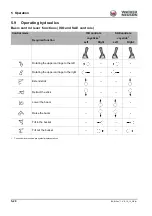
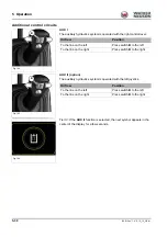
Additional control circuits
AUX I
The auxiliary hydraulics system is operated with the right control lever.
AUX II (option)
The auxiliary hydraulics system is operated with the left joystick.
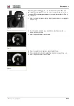
Tier IV: If the
AUX II
function is selected, the next symbol appears in the
center of the display for a few seconds.
Fig. 164
Fig. 164
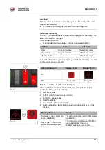
B
Oil flow
Position
To the line on the left
Press switch
B
to the left
To the line on the right
Press switch
B
to the right
B
Fig. 165
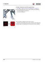
Oil flow
Position
To the line on the left
Press switch
B
to the left
To the line on the right
Press switch
B
to the right
Fig. 166
Summary of Contents for ET35
Page 14: ...1 8 BA E16 en 1 0 E16_10_100 fm 1 Foreword Notes...
Page 46: ...3 8 BA E16 en 1 0 E16_10_300 fm 3 Introduction Warning labels Fig 9 symbolic representation...
Page 64: ...3 26 BA E16 en 1 0 E16_10_300 fm 3 Introduction Notes...
Page 194: ...6 8 BA E16 en 1 0 E16_10_600 fm 6 Transportation Notes...
Page 252: ...8 8 BA E16 en 1 0 E16_10_800 fm 8 Malfunctions Notes...
Page 292: ...9 40 BA E16 en 1 0 E16_10_900 fm 9 Technical data 9 15 Dimensions ET35 symbolic representation...
Page 294: ...9 42 BA E16 en 1 0 E16_10_900 fm 9 Technical data EZ36 symbolic representation...
Page 296: ...9 44 BA E16 en 1 0 E16_10_900 fm 9 Technical data Notes...
Page 300: ...S 4 BA E16 en 1 0 E16_10_3SIX fm...


