background image

Chapter 5, Operating Instructions: Cutting the Window

E.H. Wachs

Part No. 06-030-MAN, Rev. 2-0709

33

6.

Put the spindle drive lever into the ON position to start 
the spindle drive motion.

7.

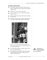
Using the supplied 1-3/8” socket, turn the spindle feed 
nut on the cutter head counter-clockwise to feed the 
blade into the pipe.

Figure 5-22.  Turn the spindle feed nut counter-clock-
wise to feed the blade into the pipe.

8.

Feed the blade in slowly. If the blade starts to chatter, 
stop for a few seconds, then resume feeding at a 
slower rate.

9.

Feed the blade in until you have penetrated the pipe 
wall. Continue feeding as far as you can without cut-
ting internal structures in the pipe.

10.

Remove the socket from the spindle feed nut.

11.

With the spindle drive still engaged and the blade turn-
ing, use the motion drive lever to start making the cut. 
The motion drive will automatically be in cutting 
(low-speed) mode while the spindle drive is running.

12.

Continue until the cut is complete. Move the motion 
drive lever to the NEUTRAL position to stop the drive 
motion.

Spindle

Feed Nut

Summary of Contents for 06-030-MAN

Page 1: ...reserved This manual may not be reproduced in whole or in part without the written consent of E H Wachs E H Wachs 600 Knightsbridge Parkway Lincolnshire IL 60069 www ehwachs com E H Wachs Part No 06 0...

Page 2: ...Window Cutter Part No 06 030 MAN Rev 2 0709 E H Wachs...

Page 3: ...ons 9 System Components 9 Window Cutter 9 Hydraulic Power Unit HPU 11 Requirements 11 Handling 11 Power Source 12 Specifications 12 Accessories 13 Chapter 4 Assembly Disassembly and Storage 15 Removin...

Page 4: ...t Stabilizing Clamp 30 Rotating the Cutter Head 31 Feeding the Cutter into the Pipe 32 Chapter 6 Routine Maintenance 35 Chapter 7 Service and Repair 37 Chapter 8 Parts Lists and Drawings 39 Chapter 9...

Page 5: ...u should read through this manual and become familiar with all instruc tions At a minimum make sure you read and understand the following chapters Chapter 1 About This Manual Chapter 2 Safety Chapter...

Page 6: ...itional information such as warnings special notes and definitions Refer to it for safety notes and other information SYMBOLS AND WARNINGS The following symbols are used throughout this manual to indi...

Page 7: ...sed chapters for your manual remove the old chapters from your binder and replace them with the new chapters When a manual is revised we will update the revision his tory on the title page and at the...

Page 8: ...Window Cutter 4 Part No 06 030 MAN Rev 2 0709 E H Wachs...

Page 9: ...w these guidelines for safe operation of any mechani cal equipment associated with the data logger Look for this sym bol throughout the manual It indicates a personal injury hazard READ THE OPERATING...

Page 10: ...ial materials out of the work area Only people directly involved with the work being performed should have access to the area Safety Symbols This icon is displayed with any safety alert that indicates...

Page 11: ...up and configuration of the machine with the power supply disconnected Connect the power sup ply when you are ready to start cutting MACHINE SAFETY NOTICE Failure to follow the instruc tions for machi...

Page 12: ...Window Cutter 8 Part No 06 030 MAN Rev 2 0709 E H Wachs...

Page 13: ...pre cisely cut through the thickness of the pipe without damag ing any internal structures The window cutter is mounted directly on a horizontal pipe For a vertical pipe a guide ring the size of the p...

Page 14: ...mponents Radial gearbox Drive control lever Chain tensioning Feed select gearbox nut Spindle motor Stabilizing wedges Manifold Cutter feed nut Spindle assembly Spindle assembly Axial drive lock nut sc...

Page 15: ...ing CAUTION Do not attempt to lift or move the window cutter by hand Use a hoist or crane The window cutter weighs approximately 400 lbs 182 kg You will need a hoist or crane to move it and position i...

Page 16: ...unit for the window cutter provides 10 gpm 38 lpm flow at 2 000 psi The HPU operates on 230 V electric power at 28 4 amps SPECIFICATIONS Length 63 160 cm Width 31 79 cm Height 13 33 cm Radial Clearan...

Page 17: ...ries E H Wachs Part No 06 030 MAN Rev 2 0709 13 ACCESSORIES Guide rings for vertical pipe 16 18 and 20 Figure 3 4 Guide ring for cutting on vertical pipe Radial cut support clamp Figure 3 5 Support cl...

Page 18: ...Window Cutter 14 Part No 06 030 MAN Rev 2 0709 E H Wachs...

Page 19: ...n a flat surface first and lift it from there with the two top hooks 3 Attach a chain or cable to each of the four lift hooks on the machine and attach the other ends to the crane Make sure the crane...

Page 20: ...e The hydraulic power unit can get wet without damage but should not be operated in standing water LONG TERM STORAGE Clean the machine thoroughly before storage If it has been used undersea spray it w...

Page 21: ...f the frame There are four positions for the tracking wheels depending on the diameter of the pipe you are cutting Figure 5 1 There are four mounting positions on the frame for the tracking wheels Tab...

Page 22: ...machine Attach the required links to each chain using the supplied master links or pins Leave the ends of the chains discon nected you will need the chain open to install it on the win dow cutter aft...

Page 23: ...ition the crane over the center of the window cut ter 3 Attach a chain or cable to each lift hook and connect them to the crane Leave the crane attached to the machine and sup porting its weight until...

Page 24: ...pipe Tighten the chain until it is snug by turning the chain tensioning nut clockwise as shown in Figure 5 11 Figure 5 3 Tighten the tensioning nut until the chain is snug 8 Install the chain at the...

Page 25: ...d indicator line on the screw 12 Lower the crane and remove the lift chains from the window cutter frame Mounting on Vertical Pipe The window cutter can be installed with either end up on a vertical p...

Page 26: ...lves of the guide ring together over the pipe at the location where the top of the machine will be located The support flange thicker side of the ring must be on the bottom as shown in fig Figure 5 6...

Page 27: ...w cutter slowly until the entire machine is off the floor 5 Position the window cutter so that the tracking wheels at the top are just above the guide ring on the pipe Figure 5 8 Set the top of the ma...

Page 28: ...de ring and thread it through the drive gears as shown in Figure 5 10 Figure 5 10 Thread the chain over the outside gears and between the inside gear and the pipe 9 Connect the ends of the chain with...

Page 29: ...ain until the chain is snug 11 Install the bottom chain in the same manner as the top chain 12 Tighten the bottom chain by turning the chain tension ing nut counter clockwise Figure 5 12 Turn the bott...

Page 30: ...on the screw 15 Remove the binding strap 16 Lower the crane and remove the lift chains from the window cutter frame Connect Power Supply 1 Connect the hoses from the power unit to the connec tors on t...

Page 31: ...oth axial cuts first then make the radial cuts at the ends Vertical Pipe When window cutting on a vertical pipe perform the side and bottom cuts first then the top cut This keeps the cutter above the...

Page 32: ...has three positions as shown in Figure 5 16 Figure 5 16 The photo shows the drive control lever at the bottom of the machine directions are reversed when the controls are at the top The spindle drive...

Page 33: ...drive is on the top in this orientation on the shorter manifold block The motion drive lever is on the bottom on the taller man ifold block When the spindle drive is engaged the motion drive is auto m...

Page 34: ...o adjust the flow control valves for the drives To adjust the flow control valve loosen the set nut behind the valve knob turn the knob then tighten the set nuts Radial Cut Stabilizing Clamp A stabili...

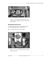
Page 35: ...across the frame at the cutting head to reduce vibrations dur ing a radial cut Rotating the Cutter Head The entire cutter head rotates to set the cutting direction Use the following procedure to rota...

Page 36: ...irst feed the cutter blade into the pipe 1 Make sure the spindle drive lever is in the OFF posi tion and the motion drive lever is in the NEUTRAL center position 2 Turn on the hydraulic power unit and...

Page 37: ...f the blade starts to chatter stop for a few seconds then resume feeding at a slower rate 9 Feed the blade in until you have penetrated the pipe wall Continue feeding as far as you can without cut tin...

Page 38: ...d nut clockwise to retract the blade from the pipe Be sure to retract the blade completely 14 Turn off the spindle drive motion 15 Position the cutter head for the next cut using the drive select leve...

Page 39: ...Chapter 6 Routine Maintenance E H Wachs Part No 06 030 MAN Rev 2 0709 35 Chapter 6 Routine Maintenance Grease the machine using Phillips 66 X C 22CF Aviation Grease or equivalent...

Page 40: ...Window Cutter 36 Part No 06 030 MAN Rev 2 0709 E H Wachs...

Page 41: ...7 Service and Repair E H Wachs Part No 06 030 MAN Rev 2 0709 37 Chapter 7 Service and Repair Refer to the drawings and parts lists in Chapter 8 for service and repair information on window cutter com...

Page 42: ...Window Cutter 38 Part No 06 030 MAN Rev 2 0709 E H Wachs...

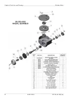
Page 43: ...8 Parts Lists and Drawings E H Wachs Part No 06 030 MAN Rev 2 0709 39 Chapter 8 Parts Lists and Drawings Refer to the drawing and the parts list on the following pages for ordering spare and replaceme...

Page 44: ...Chapter 8 Parts Lists and Drawings Window Cutter 40 06 030 MAN E H Wachs Company...

Page 45: ...Window Cutter Chapter 8 Parts Lists and Drawings E H Wachs Company 06 030 MAN 41...

Page 46: ...Chapter 8 Parts Lists and Drawings Window Cutter 42 06 030 MAN E H Wachs Company...

Page 47: ...Window Cutter Chapter 8 Parts Lists and Drawings E H Wachs Company 06 030 MAN 43...

Page 48: ...Chapter 8 Parts Lists and Drawings Window Cutter 44 06 030 MAN E H Wachs Company...

Page 49: ...Window Cutter Chapter 8 Parts Lists and Drawings E H Wachs Company 06 030 MAN 45...

Page 50: ...Chapter 8 Parts Lists and Drawings Window Cutter 46 06 030 MAN E H Wachs Company...

Page 51: ...Window Cutter Chapter 8 Parts Lists and Drawings E H Wachs Company 06 030 MAN 47...

Page 52: ...Chapter 8 Parts Lists and Drawings Window Cutter 48 06 030 MAN E H Wachs Company...

Page 53: ...E H Wachs Part No 06 030 MAN Rev 2 0709 49 Chapter 9 Accessories and Spare Parts The following accessories are provided with the window cutter Guide rings for vertical pipe 16 18 and 20 Figure 9 1 Gu...

Page 54: ...Window Cutter 50 Part No 06 030 MAN Rev 2 0709 E H Wachs Radial cut support clamp Figure 9 2 Support clamp for reducing vibration dur ing radial cuts...

Page 55: ...parts refer to the parts lists in this chapter Please provide the part description and part number for all parts you are ordering REPAIR INFORMATION Please call us for an authorization number before r...

Page 56: ...mplete it WARRANTY INFORMATION Enclosed with the manual is a warranty card Please fill out the registration card and return to E H Wachs Retain the owner s registration record and warranty card for yo...

Reviews: