waclighting.com
Phone (800) 526.2588
Fax (800) 526.2585
Headquarters/Eastern Distribution Center
44 Harbor Park Drive
Port Washington, NY 11050
Central Distribution Center
1600 Distribution Ct
Lithia Springs, GA 30122
Western Distribution Center
1750 Archibald Avenue
Ontario, CA 91760
WAC Lighting retains the right to modify the design of our products at any time as part of the company's continuous improvement program.
PREPARATION
1.
Shut off the power at the circuit breaker and remove existing fixture, including the crossbar.
2.
Carefully unpack your new fixture and lay out all the parts on a clear area. Be careful not to lose any sm
all parts necessary for
installation.
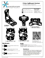
MOUNTING THE FIXTURE
(Fig. 1)
3.
Remove the mounting screw (E) from the mounting back plate.
4.
Drill holes in the wall aligned with the key holes located in the mounting back plate, insert the plastic anchors (D).
5.
Secure the mounting plate to the junction box using junction box screws (B), fasten it to the wall using wood screws (C). The side of
the mounting back plate marked “GND” must face out.
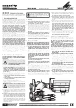
CONNECTING THE WIRES
(Fig. 2)
6.
Connect the driver input/output wires to junction box wires as shown in
Fig. 2, making sure that all wire connectors (A) are secured. If your outlet
box has a green or bare copper ground wire, connect the fixture’s ground
wire to it. Otherwise, connect the fixture’s ground wire directly to the
back plate using the green screw provided. After wires are connected,
tuck them carefully inside the junction box.
* Requires Driver to be recessed within the junction box.
COMPLETING THE INSTALLATION
(Fig. 1)
7. Secure the fixture to the mounting back plate using the mounting screw (E).
4 1/8”
1 3/4”
Fixture Wires
Black or
Smooth
Fixture Wires
White or
Ribbed
Fixture Wires
Bare wire
(Ground)
House Wires
Black
(Hot)
House Wires
White
(Neutral)
House Wires
Green or Bare Copper
(Ground)
Fig.2 Wiring
Junction Box
Wire Connector
Driver
w-Y
w8Y
w)
Plastic Anchor
Mounting
#BDL
Plate
Wood Screw
Mounting Screw
'JYUVSF
A
D
C
E
WAC Lighting retains the right to modify the design of our products at any time as part of the company's continuous improvement program.
G0
Ground Wire Screw
/;:;+'ULYHU
3.
Remove
the
mounting
screw
(
C
)
from
the
fixture.
5
.
Secure
the
mounting
back
p
l
ate
to
the
junction
box
using
junction
box
screws
(
B
)
.
T
he
side
of
the
mounting
back
p
l
ate
marked
“GN
D
”
must
face
out.
6
.
Secure
the
canopy
to
the
mounting
p
l
ate
using
the
mounting
screw
(
C
)
.
4
.
Connect
the
D
river’s
input
wires
to
junction
box
wires
as
shown
in
F
ig.
2
,
making
sure
that
a
ll
wire
connectors
(
A
)
are
secured.
If
your
out
l
et
box
has
a
green
or
bare
copper
ground
wire,
connect
the
fixture’s
ground
wire
to
it.
Otherwise,
connect
the
fixture’s
ground
wire
direct
l
y
to
the
back
p
l
ate
using
the
green
screw
provided.
After
wires
are
connected,
tuck
them
carefu
ll
y
inside
the
junction
box.
CONNECTING THE WIRES (Fig. 2)
1
.
Shut
o
ff
the
power
at
the
circuit
breaker
and
rem
ove
existing
fixture,
inc
l
uding
the
crossbar.
2
.
Carefu
ll
y
unpack
your
new
fixture
and
l
ay
out
a
ll
the
parts
on
a
c
l
ear
area.
Be
carefu
l
not
l
ose
any
sma
ll
parts
necessary
for
insta
ll
ation.
PREPARATION
MOUNTING THE FIXTURE(Fig.1)
7
.
T
here
is
optiona
l
meta
l
c
l
ip
in
hardware
bag,
remove
the
screw
(D)
to
rep
l
ace
the
p
l
astic
c
l
ip,
secure
the
meta
l
c
l
ip
with
screw
(D)
.
Fixture Wires
B
l
ack
or
Smooth
Fixture Wires
W
hite
or
Ribbed
Fixture Wires
Bare
wire
(
Ground
)
House Wires
B
l
ack
(
Hot
)
House Wires
W
hite
(
Neutra
l)
House Wires
Green
or
Bare
Copper
(
Ground
)
Fig.2 Wiring
10 5/16"
3.
Remove
the
mounting
screw
(
C
)
from
the
canopy.
6
.
Secure
the
mounting
back
p
l
ate
to
the
junction
box
using
junction
box
screws
(
B
)
.
T
he
side
of
the
mounting
back
p
l
ate
marked
“GN
D
”
must
face
out.
4
.
Adjust
the
fixture
wire
l
ength
by
pushing
the
cab
l
e
gripper
on
the
canopy
and
pu
ll
ing
the
wire
as
desired.
M
ake
sure
the
wires
are
the
same
l
ength.
5
.
Connect
the
D
river’s
input
wires
to
junction
box
wires
as
shown
in
F
ig.
2
,
making
sure
that
a
ll
wire
connectors
(
A
)
are
secured.
If
your
out
l
et
box
has
a
green
or
bare
copper
ground
wire,
connect
the
fixture’s
ground
wire
to
it.
Otherwise,
connect
the
fixture’s
ground
wire
direct
l
y
to
the
back
p
l
ate
using
the
green
screw
provided.
After
wires
are
connected,
tuck
them
carefu
ll
y
inside
the
junction
box.
CONNECTING THE WIRES (Fig. 2)
1
.
Shut
o
ff
the
power
at
the
circuit
breaker
and
rem
ove
existing
fixture,
inc
l
uding
the
crossbar.
2
.
Carefu
ll
y
unpack
your
new
fixture
and
l
ay
out
a
ll
the
parts
on
a
c
l
ear
area.
Be
carefu
l
not
l
ose
any
sma
ll
parts
necessary
for
insta
ll
ation.
PREPARATION
MOUNTING THE FIXTURE(Fig.1)
Fixture Wires
B
l
ack
or
Smooth
Fixture Wires
W
hite
or
Ribbed
Fixture Wires
Bare
wire
(
Ground
)
House Wires
B
l
ack
(
Hot
)
House Wires
W
hite
(
Neutra
l)
House Wires
Green
or
Bare
Copper
(
Ground
)
Fig.2 Wiring
Ground Wire Screw
Plate
7
.
Hook
the
safety
cord
to
the
mounting
p
l
ate.
8
.
Secure
the
canopy
to
the
mounting
p
l
ate
using
the
mounting
screw
(
C
)
.
Junction Box
Wire Connector
$
0RXQWLQJ3ODWH
&
$OOHQ6FUHZ
Canopy
Junction Box Screw
Mounting Screw
Input Wires
%
'
$OOHQ :UHQFK
4
.
Secure
mounting
p
l
ate
to
the
junction
box
using
junction
box
screws
(
B
)
.
T
he
side
of
the
mounting
p
l
ate
marked
“GN
D
”
must
face
out.
5
.
Pl
ace
the
canopy
over
the
mounting
p
l
ate
and
secure
with
mounting
screws.
3.
Connect
the
fixture
wires
with
supp
l
y
wires
as
shown
in
F
ig.
2
,
making
sure
a
ll
wire
connector
(
A
)
are
secured.
If
your
out
l
et
box
has
a
green
or
bare
copper
ground
wire,
connect
the
fixture’s
ground
wire
to
it.
Otherwise,
connect
the
fixture’s
ground
wire
direct
l
y
to
the
mounting
p
l
ate
using
the
green
screw
provided.
After
a
ll
wires
are
connected,
tuck
them
carefu
ll
y
inside
the
junction
box.
CONNECTING THE WIRES (Fig. 2)
1
.
Shut
off
the
power
at
the
circuit
breaker
and
remove
existing
fixture,
inc
l
uding
the
crossbar.
2
.
Carefu
ll
y
unpack
your
new
fixture
and
l
ay
out
a
ll
the
parts
on
a
c
l
ear
area.
Be
carefu
l
not
l
ose
any
sma
ll
parts
necessary
for
insta
ll
ation.
PREPARATION
MOUNTING THE FIXTURE (Fig. 1)
6
.
T
wist
l
ock
the
acry
l
ic
shade
into
the
canopy,
then
l
ock
it
with
a
ll
en
screw
(
C
)
using
a
ll
en
wench
(D)
.
Fixture Wires
B
l
ack
or
Smooth
Fixture Wires
W
hite
or
Ribbed
Fixture Wires
Bare
wire
(
Ground
)
House Wires
B
l
ack
(
Hot
)
House Wires
W
hite
(
Neutra
l)
House Wires
Green
or
Bare
Copper
(
Ground
)
Fig.2 Wiring
Ø4"
Mounting Plate Dimensions
7MBC101501
1 3/4”
1 3/8”
FIG.1
INSTALLATION INSTRUCTIONS
578 - LED Outdoor
FM-W57806/FM-W57809/FM-57812/FM-W57906F
/FM-W57809F/FM-57812F