


35
Diagnostics, Troubleshooting and Testing
6.5.6 Right Turn Signal Activation Input
If the vehicle uses the WABCO OnGuard display, whether on the dash or behind/under the dash, it will
need to receive a "Right Turn Signal Activation" signal. This can be performed by the OnSide BSD radar
sensor in one of two ways.
Through a direct wire input from the turn signal circuit using a relay.
Through the vehicle J1939 circuit using the "Turn Signal Switch" parameter in the "Operators External
Light Controls" message.
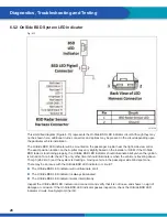
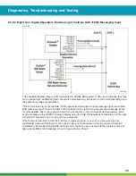
6.5.6.1 Right Turn Signal Relay Input
Fig. 6.19
4016867b
This simplifi ed diagram (Figure 6.19) represents the right turn signal relay circuit. Although they may not
be shown here, additional in-line connectors and splices may be present in the circuit depending upon the
particular vehicle and installation.
If the OnSide BSD system was installed as an "Add-On" or "Aftermarket" kit, the relay will be
tapped into the OnSide BSD system harness and will have a relay pin numbers 1, 2, 3 and 5.
If the vehicle is equipped the WABCO OnGuard display and uses the direct wire input system, the OnSide
BSD radar sensor needs to see ground at pin 9 to recognize that the right turn signal has been activated.
If the vehicle does use the right turn signal relay input and no chirp or visual warning comes from the
WABCO OnGuard display when the vehicle is traveling above 15 mph (24.2 km/h) with the right turn signal


