WABCO OnGuard Maintenance Manual Download Page 10

1   

Introduction

3

WABCO

 Maintenance Manual MM-1306 (Revised 08-18)

Collision Warning and Mitigation

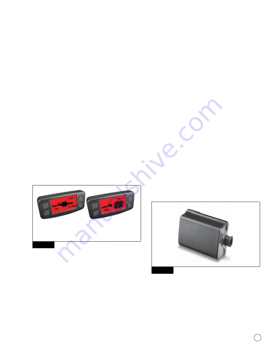
When an unforeseen event occurs, such as another vehicle enters 
the vehicle’s lane traveling slower than the vehicle, or the gap 
between the vehicles becomes too close, the CMS will provide an 
audible alert and the display will turn red with a collision warning 
symbol. If the system determines that a rear-end collision is 
imminent, it will automatically apply the brakes to reduce the 
vehicle’s speed. The driver may also feel a haptic warning (short 
brake pulse) to warn of collision danger. 

The driver

 must also take 

the appropriate corrective action to avoid dangerous driving 
situations. Figure 1.5.

The OnGuard™ CMS will not be active when the vehicle’s speed is 
below 15 mph. If the OnGuard™ CMS detects a stationary object in 
the vehicle’s lane (such as a disabled car) it will provide an audible 
alert and the display will turn red showing a stationary object 
symbol. 

The OnGuard™ CMS will not apply the brakes or 

reduce the vehicle’s speed when it detects a stationary object.

The OnGuardACTIVE™ CMS will not be active when the vehicle’s 
speed is below 15 mph or over 77 mph. If the OnGuardACTIVE™ 
CMS detects a stationary object (such as a disabled car) it will 
provide an audible alert, followed by a haptic warning and then a 
brake application to reduce the vehicle’s speed.

Figure 1.5

System Limitations

OnGuard™ and OnGuardACTIVE™ CMS only brake for moving 
objects located directly in front of your vehicle. The OnGuard™ 
CMS does not operate when your speed is below 15 mph. The 
OnGuardACTIVE™ CMS does not operate when your speed is below 
15 mph or over 77 mph. Accordingly, the CMS:

Will not react and alert the driver to objects crossing in front of 
the vehicle or oncoming traffic.

Should not be relied on to track lead vehicles when traveling 
through a severe curve in the road. Because of this, ACC is not 
recommended for use on winding (curving) roads.

Should not be relied upon to track smaller objects (e.g. 
motorcycles, mopeds, bicycles, pedestrians, etc.).

Should not be relied on to alert drivers to vehicles in an adjacent 
lane.

Will alert but not actively brake on stationary objects.

System Components

Radar Sensor

The radar sensor is used to detect vehicles and obstacles for the 
OnGuard™ Collision Mitigation System. It is mounted in the front of 
the vehicle near the center of the bumper and recessed in the 
bumper in most applications. Figure 1.6. The sensor has an 
electrical connector that provides power, ground and 
communication to the SAE J1939 network which is required for 
correct operation.

The mounting orientation is determined by the 3 hole bolt pattern of 
the bracket. The radar sensor generally is mounted with the 
connector on the driver’s side of the vehicle. The sensor connector 
is protected by a rubber boot. This boot should fully cover the 
connector upon completion of the sensor installation or repair.

Figure 1.6

Fascia

The fascia is a protective cover for the radar sensor and is 
assembled to the same bracket on which the radar sensor is 
mounted. Some vehicle manufacturer’s use other fascia designs. 
Only original equipment fascias supplied by WABCO and the vehicle 
manufacturer may be used to protect the radar sensor. Figure 1.7.

Figure 1.5

40118

6

0

a

Object

Collision Warning

Stationary

Collision Warning

Figure 1.6

4010334

a

Summary of Contents for OnGuard

Page 1: ...OnGuard AND OnGuardACTIVE COLLISION MITIGATION SYSTEMS MAINTENANCE MANUAL...

Page 2: ...tools when required to help avoid serious personal injury and damage to components Hazard Alert Messages and Torque Symbols WARNING A Warning alerts you to an instruction or procedure that you must f...

Page 3: ...stem CMS under the following conditions Weather such as rain sleet snow ice heavy fog as well as smoke or dust These conditions can make roads slippery which can cause a spinout or block or limit the...

Page 4: ...will not track vehicles or operate Make sure that the Service Alignment procedure is completed before releasing the vehicle from service Failure to do so can result in serious personal injury or deat...

Page 5: ...nGuard CMS will have limited or no functionality which can lead to an accident Serious personal injury or death and or severe property damage can result WARNING The OnGuard CMS requires time to recogn...

Page 6: ...at are in your lane or is tracking vehicles that are not in your lane the radar may not be aligned correctly If this occurs immediately have the OnGuard CMS radar inspected and corrected as needed Ref...

Page 7: ...r and Display Software Levels Error Screens and Diagnostic Trouble Codes Required Maintenance 6 Troubleshooting Guide 10 TOOLBOX Software 12 OnGuard and OnGuardACTIVE Radar Diagnostic Trouble Code Tab...

Page 8: ...sion still exists and the driver has not taken the appropriate action the CMS will request application of the foundation brakes to provide up to 50 of available braking power When the CMS requests app...

Page 9: ...ure 1 2 Figure 1 2 Following Distance Alert Adaptive Cruise Control Not Set The Following Distance Alert will provide an audible alert and the in cab dash display screen will turn yellow if the vehicl...

Page 10: ...he OnGuardACTIVE CMS does not operate when your speed is below 15 mph or over 77 mph Accordingly the CMS Will not react and alert the driver to objects crossing in front of the vehicle or oncoming tra...

Page 11: ...at the OnGuard system is tracking The functions of the OnGuard display may be integrated into a vehicle s instrument panel If the vehicle has an integrated display please refer to your vehicle owner s...

Page 12: ...ctions or the CMS functions Multiple DTCs may be active simultaneously If a DTC is shown on the display use the UP and DOWN keys on the display to scroll through each code Figure 2 2 Record each DTC f...

Page 13: ...his can be caused by problems in the electrical harness or a faulty display Refer to Display Harness Electrical Checks in the Electrical System and Harness Troubleshooting Section If the display light...

Page 14: ...adar and fascia Blocked Radar not aligned Perform Radar Sensor Service Alignment using TOOLBOX Software Ignition cycle may be required to clear the fault and restore system function Radar Sensor Align...

Page 15: ...son for disabled CMS TOOLBOX Software and Diagnostic Trouble Code Table Communication between the radar and display is interrupted Troubleshoot harnesses between radar and display Diagnose J1939 wirin...

Page 16: ...on the mounting bracket The radar sensor may be too close to or actually contacting the bumper as mounted which will affect the radar signal There should be at least 1 4 inch of clearance between the...

Page 17: ...ted under Adapter selection in Utilities If the protocol was changed you will need to cycle the key This will display the radar sensor part number and radar software version as well as other important...

Page 18: ...y repairs use the Clear DTCs to reset the radar 4 A DTC report can also be generated by selecting the Generate DTC Report button while in the Diagnostic Trouble Codes screen A Save As screen will then...

Page 19: ...OnGuard and OnGuardACTIVE Radar Diagnostic Trouble Code Table The following table provides repair instructions and the corresponding Troubleshooting Sections in this manual for SPN FMI DTCs that are...

Page 20: ...is used on the vehicle 188 9 J1939 Engine Configuration 1 EC1 message not received or intermittent Cycle the ignition to clear DTCs after engine servicing Verify engine ECM is functional and has corr...

Page 21: ...fy transmission ECU is functional and has correct software and 527 parameters 527 9 J1939 Cruise Control Vehicle Speed 1 CCVS1 message from the primary source usually the engine not received or interm...

Page 22: ...twork engine ECM body cab or chassis controller is functional Verify the correct radar part number is installed on the vehicle 598 19 Incorrect J1939 Clutch Switch data received in CCVS1 message from...

Page 23: ...ge from the ABS not received or intermittent Verify the ABS ECU is connected to the J1939 network and is functional Verify correct ABS part number is used Cycle ignition to clear DTCs after ABS servic...

Page 24: ...ge from the display or instrument cluster not received or intermittent Intermittent power or J1939 network connection to display or instrument cluster Verify harness is correct Verify correct software...

Page 25: ...ader error usually caused when there is an issue during a radar software update Run the software update again Is usually seen in WABCO TOOLBOX Software PC Diagnostics with SPN 197120 FMI 31 on the dis...

Page 26: ...sed the system to be temporarily disabled Use WABCO TOOLBOX PC Diagnostics to test the Anti Lock Braking System Verify the correct radar part number is installed on the vehicle Verify the correct ABS...

Page 27: ...lear the secondary DTC 517505 13 VDY velocity correction factor is Out of Range Check speed signal parameters in engine braking system and tachograph 517525 13 Unknown error during alignment Software...

Page 28: ...or marker light bulb Inspect the radar connector for corrosion Inspect each of the power connections between the ignition switch and the radar to determine where loss of power may be occurring 517559...

Page 29: ...of range for more than 5 minutes Verify no visible physical damage to radar Check power ground and load test at the radar harness connector If fault persists after completing previous checks and repai...

Page 30: ...onitors and utilizes other system messages on the J 1939 network allowing it to function without interfering with vehicle stability systems and engine transmission speed parameters The OnGuard and OnG...

Page 31: ...following although not all inclusive is a list of service maintenance and repair operations requiring system Service Alignment Chassis parts replacement Steering or suspension parts replacement adjust...

Page 32: ...2 17 appears in the display This typically takes less than 10 miles to complete Figure 2 17 5 After completing the Service Alignment procedure the system returns to one of the normal operating screens...

Page 33: ...ehicle chassis causing the CMS to malfunction The harness is especially susceptible to wear when the harness rubs against a sharp edge Both wire fatigue and harness abrasion can be prevented by correc...

Page 34: ...ne retarder or driveline retarder ECUs have been re flashed with new software that is incorrect was not downloaded correctly or has the incorrect parameter set This information may reside in the vehic...

Page 35: ...t the DTC has been cleared Cruise Control System Troubleshooting Refer to the Diagnostic Trouble Code Table for further information The following are the troubleshooting sections and sub sections refe...

Page 36: ...dar connector 5 Remove the radar sensor from the radar sensor bracket by removing the three nuts on the rear of the radar sensor bracket 6 Verify that the mounting bracket bolts are securely tightened...

Page 37: ...e 3 2 3 Remove the display Save the hardware for installation of the new display 4 Reinstall the new display 5 Connect the wiring connector to the new display 6 Reassemble the instrument cluster panel...

Page 38: ...s in 40 countries For more information visit www wabco na com NYSE WBC is a leading global supplier of technol ogies and services that improve the safety efficiency and con nectivity of commercial veh...

Reviews: