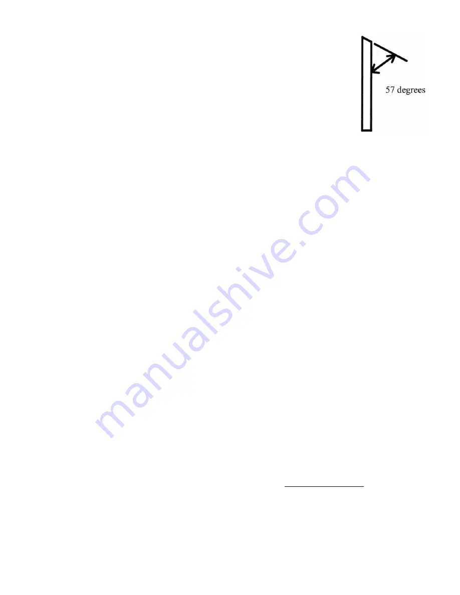
Both molding and planing knives have an edge angle of 57 degrees measured off the back
of the knife. Hook angle is 11 degrees
The use of dull knives will put a strain on the feed mechanism and will result in your
need of a repair. Any problems created due to the use of dull knives are not covered
under the warranty.
Face of knife →
HOW TO MOLD
1.
A
sub-plate
made of knife millable material will be needed on any job where the knife is designed to
cut below the bottom of the stock. This type of knife will hit the base of the machine if a sub-plate is not
used. An example of this situation would be the molding of half or quarter rounds .
2. If the knife comes close to the base of the machine, such as the bottom knife of any crown or bed
moldings, a sub-plate should be used to prevent damage in case of accidental depression of the head,
which would plunge the knife into the base. Our optional GS-2 guide system has a sub-plate built into it,
a fixed guide, flex guide, and ratchet handles, all for a very reasonable price.
3. A basic set of guides has been shipped with your machine. Place a sample piece of stock on the bed and
roll the knife profile to contrast against the stock and align the stock to the position you want it to run.
Lower the head to grip the stock with the rollers and set your solid guide and then set your flex guide
with a little tension. You may fashion a sub plate yourself and clamp it to the machine base. When using
a sub-plate, always remember to add its thickness to the stock thickness when setting machine height.
You will need longer “C” clamps when using a sub plate. See the guide section for more info.
4. Stock height should be uniform in size and to within 1/32” of finished molding size.
5. Stock width should be uniform and not extend beyond knife edges. Saw ripping to width will not make
the stock uniform enough for smooth flow through the guides, and thus, will not result in a satisfactory
molding. We recommend that all stock be planed in both width and height to near finished molding size
before setting up to do the profile.
6. When tightening the knives, push them firmly against the lip and sideways against the bolts in the
direction of the tube side of the machine for an exact profile match up. Hold secure while tightening
bolts.
7. Set the head height to within 3/16”of your stock height measured off the bed of the machine. If using a
sub-plate you must compensate for it’s thickness off the bed in your head setting calculation. This will
give you proper roller tension on your molding stock. This is the correct way to mold. It is acceptable to
leave 3/16” of the cut for multiple passes. But for safety reasons leave no more than 3/16”. Failure to set
your head height within 3/16” of the stock height will create an extreme safety hazard in that possibly
not enough roller pressure will be applied, or that no roller pressure at all will be applied
Example
,
You want to take a first cut at 3/16” above the “full cut” setting. You have a ½” sub plate on
the machine bed and you are molding a ¾” piece of stock. You set the machine head at 1 7/16”, adding
½” + ¾” + 3/16” = 1 7/16”. After this first pass you may take three more passes at 1/16” each to get to
“full profile cut”, or two passes at 3/32” each, etc. A complete revolution of the elevation handle is equal
to 3/32” in knife height.
5
Summary of Contents for 154
Page 15: ...GEAR BOX SHAFT ASSEMBLIES 15...
Page 16: ...GEAR BOX ASSEMBLY VIEW 16...
Page 17: ...ARBOR REMOVAL VIEW 17...


