background image

STARTING YOUR INSTALLATION 
 

Installation time: Approximately 60 minutes 
 
Mount the Power Distribution Center (PDC) 


Choose a suitable location to mount the PDC.  The ideal location is in the 

rear of the truck inside the toolbox.  The four mounting feet can be mounted to 
the sides or the top and bottom of the PDC enclosure.  It is best to mount the 
PDC with the strain reliefs and wired/wireless button facing down.  Remove the 
cover from the PDC. 

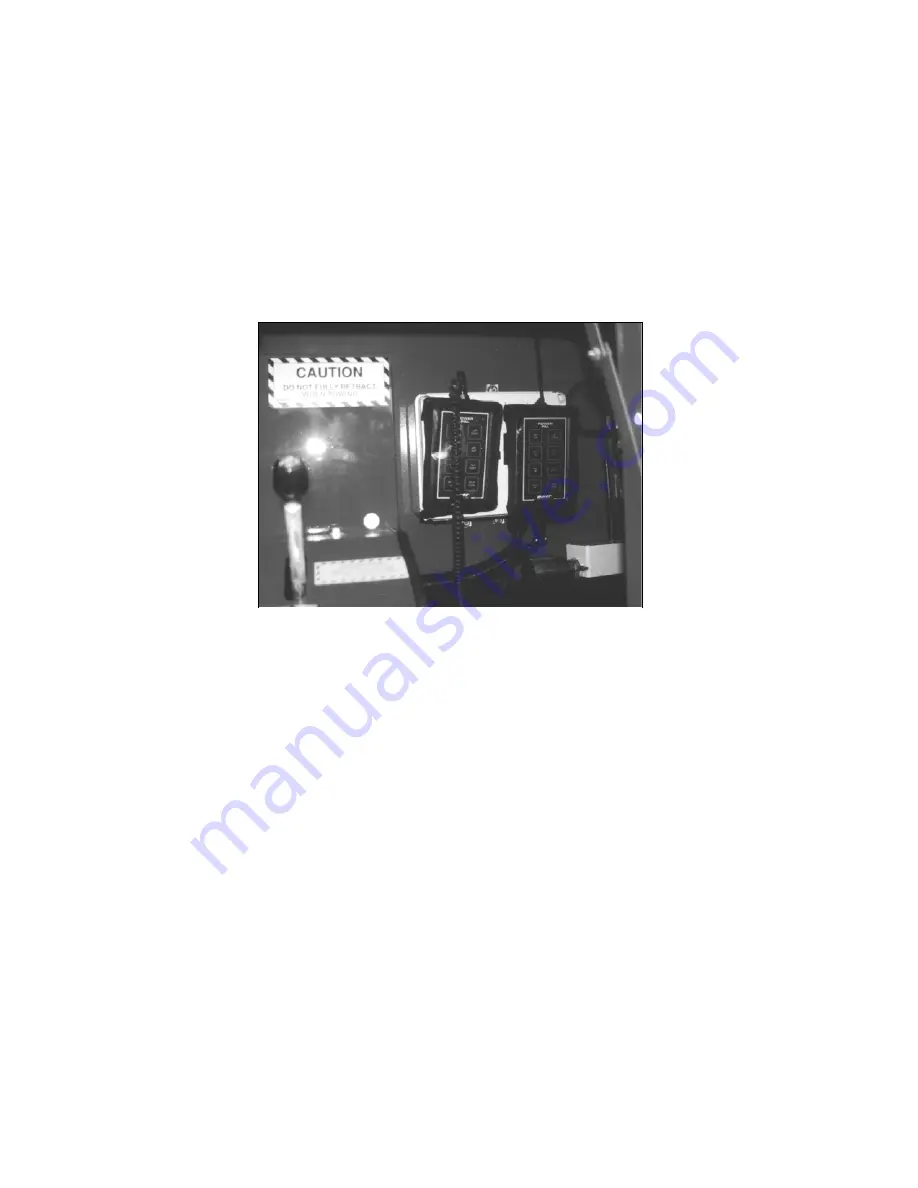
Typical mounting location of Power Pal™ 


NOTE:  Leave enough clearance to route all of your input and 
output wires to the PDC enclosure. 


Install the Output Harness w/Power Wires 


Connect the output harness to the 16 pin Amp connector.  The color code 

chart on page 5 describes the color codes and functions of the output harness.  
The power wires are also included in the harness, the #10 AWG BLACK wire is 
for ground (-GND), the #10Awg RED is for power (+12V). 
Take caution when connecting the power wires and the output wires. Incorrect 
connections may cause harm to the unit. 
 

Connect the ground wire 


Connect the #10 AWG black ground wire from the harness to the ground 

terminal inside the PDC.  Attach the opposite end of the black ground wire to the 
J-Box  ground connection or a clean metal to metal chassis ground, tighten 
securely. 

IMPORTANT- 

(

Do not connect to the sub frame, but to the truck’s chassis)  

Protect the chassis ground connection with a light coating of grease to prevent 
corrosion.   


Summary of Contents for POWER PAL V-16

Page 1: ...POWER PAL WIRED WIRELESS REMOTE ELECTRIC HYDRAULIC CONTROLLER MODEL V 16 POWER UP PRODUCTS 76 Hardy Drive Sparks NV 89431 775 336 2400 READ ME FIRST OR VOID YOUR WARRANTY COPYRIGHT 01 January 2004 ...

Page 2: ...AL KIT INCLUDES THE FOLLOWING WIRED 15 FUNCTION REMOTE KEYPAD WITH 25ft HEAVY DUTY COILED CORD HARNESS V 16 PP 05 2 pcs POWER DISTRIBUTION CENTER ENGINE KILL RELAY MOUNTING FEET AND SCREWS WARRANTY CARD BACK OF MANUAL MODEL V 16 REVISION 1 January 2004 2 ...

Page 3: ...Wires Connect the output harness to the 16 pin Amp connector The color code chart on page 5 describes the color codes and functions of the output harness The power wires are also included in the harness the 10 AWG BLACK wire is for ground GND the 10Awg RED is for power 12V Take caution when connecting the power wires and the output wires Incorrect connections may cause harm to the unit Connect the...

Page 4: ...he green LED on the circuit board does not come on consult the troubleshooting section and correct the problem before proceeding Make sure that the wired wireless switch is in the wired position A green indicator light on the top right corner of the wired remote keypad will light If it does not consult the troubleshooting section on page 8 Check the operation of the wired remote keypad Press each ...

Page 5: ...LLOW RIGHT WINCH OUT GREEN AUX 1 WHITE ENGINE KILL ORANGE AUX 2 PINK AUTOTHROTTLE NOTES OF CONCERN 1 The maximum amperage on any output must be no more than 5 amps The electric over hydraulic solenoids does not require more than 5 amps to operate 2 Overdriving an output will cause the output to temporarily cease function RED LED should be on Correct the problem and test for proper function 3 Overl...

Page 6: ...functionality of the system Make sure that each button on the keypad turns on the correct output If the function does not come on check the indicator LED at the output on the PDC circuit board If the red LED comes on when you press a button there is an overload or short circuit in the wiring for that output Locate and correct the problem as necessary If all outputs function correctly turn off powe...

Page 7: ...pad will be off and the wired remote will not function The transmitter keypad will not display a green power light like the wired keypad The wireless keypad will display a RED flashing light when the positions are activated on the keypad Located on the receiver board is the programming button Press the programming button and hold down The RED LED indicator on the receiver board will turn on solid ...

Page 8: ...NOTE The wired keypad and the wireless keypad will not operate at the same time This completes the installation of the Power Pal Wireless System 8 ...

Page 9: ...wires are properly connected to their destination Check suspected output wire for a secure connection at the output stab of the PDC circuit board Short or overload condition While pressing the position on the keypad look at the indicator LED on the PDC board that is associated with the suspected function If the RED LED is lit there is an overload condition or a short circuit in the output wiring C...

Page 10: ...your antenna for loose connections kinked cable broken cabling or excess cable that is coiled Check the status of your batteries Replace them with fresh alkaline AA batteries I programmed the receiver to the transmitter but the unit still won t function Check to make sure the wired wireless switch is in the wireless position Try moving around the vehicle and operating the transmitter If the unit o...

Page 11: ...s the same function that is intermittent check the output wire coming from the Power Pal to the distant function NOTE If there is another truck that is operating wireless nearby the two signals will cancel each other becoming intermittent or cease to operate If you need further assistance our technical assistance department can be reached Monday through Friday 8 00 a m to 4 00 p m Pacific Time 775...

Page 12: ... Serial Numbers PDC serial number ______________________________________ Wired Keypad serial number _______________________________ Wireless Keypad serial number _____________________________ Purchased From Name ___________________________________________________ Address__________________________________________________ City ______________________State___________Zip Code ________ Date of Purchase ...

Reviews: