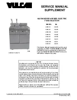
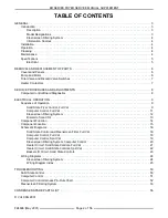


ER SERIES FRYER SERVICE MANUAL SUPPLEMENT - REMOVAL AND REPLACEMENT OF PARTS
F24696 (May 2001)
Page 6 of 56
REMOVAL AND REPLACEMENT OF PARTS
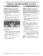
COVERS AND PANELS
WARNING: DISCONNECT THE ELECTRICAL
POWER TO THE MACHINE AT THE MAIN
CIRCUIT BOX. THERE ARE SEVERAL SEPARATE
CIRCUITS. BE SURE ALL ARE DISCONNECTED.
PLACE A TAG ON THE CIRCUIT BOX(ES)
INDICATING THE CIRCUIT IS BEING SERVICED.
Front Control Panel
1. Open the cabinet door to the fryer section being
serviced.
2. Remove the screws along the bottom lip and
along the top of the of the control panel.
3. Work the panel loose at each end and lift off.
4. Reverse procedure to install.
Basket lift Covers
1. Loosen bolt at the top of each basket lift hanger
and lift the basket hangers from the support rod.
2. Remove the screws that secure the lower cover
at the rear of the fryer section.
3. Remove the screws along each side of the
cover.
4. Lift the cover and place to the side.
5. Reverse procedure to install.
PUMP AND MOTOR
WARNING: DISCONNECT THE ELECTRICAL
POWER TO THE MACHINE AT THE MAIN
CIRCUIT BOX. THERE ARE SEVERAL SEPARATE
CIRCUITS. BE SURE ALL ARE DISCONNECTED.
PLACE A TAG ON THE CIRCUIT BOX(ES)
INDICATING THE CIRCUIT IS BEING SERVICED.
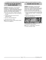
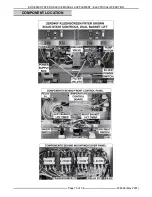
NOTE: Refer to component location picture 6100 for
location of pump motor.
1. Open the right side cabinet door of the filter
section.
2. Pull the filter drawer out, remove the filter tank
assembly and push the tank support arms back
underneath the fryer.
3. Disconnect the electrical connection to the
motor.
NOTE: The remaining steps are written for front
removal of the pump assembly. If access to the
back of the fryer is available, it may be easier to
remove the pump from the rear.
4. Separate the swivel hose connection on the right
side (intake) of the pump.
5. Separate the swivel hose connection on the left
side (discharge) of the pump.
6. Remove the mounting bolts from the motor.
7. Remove the motor, pump and piping assembly.
A.
If replacing the pump and motor, remove
the existing piping assemblies and reuse.
8. Reverse procedure to install.
NOTE: Ensure the rubber vibration pad or the
grommets are installed under the motor mounting
plate.
Summary of Contents for 126905
Page 26: ...ER SERIES FRYER SERVICE MANUAL SUPPLEMENT ELECTRICAL OPERATION F24696 May 2001 Page 26 of 56 ...
Page 27: ...ER SERIES FRYER SERVICE MANUAL SUPPLEMENT ELECTRICAL OPERATION F24696 May 2001 Page 27 of 56 ...
Page 28: ...ER SERIES FRYER SERVICE MANUAL SUPPLEMENT ELECTRICAL OPERATION F24696 May 2001 Page 28 of 56 ...
Page 29: ...ER SERIES FRYER SERVICE MANUAL SUPPLEMENT ELECTRICAL OPERATION F24696 May 2001 Page 29 of 56 ...
Page 30: ...ER SERIES FRYER SERVICE MANUAL SUPPLEMENT ELECTRICAL OPERATION F24696 May 2001 Page 30 of 56 ...
Page 31: ...ER SERIES FRYER SERVICE MANUAL SUPPLEMENT ELECTRICAL OPERATION F24696 May 2001 Page 31 of 56 ...
Page 32: ...ER SERIES FRYER SERVICE MANUAL SUPPLEMENT ELECTRICAL OPERATION F24696 May 2001 Page 32 of 56 ...
Page 33: ...ER SERIES FRYER SERVICE MANUAL SUPPLEMENT ELECTRICAL OPERATION F24696 May 2001 Page 33 of 56 ...
Page 34: ...ER SERIES FRYER SERVICE MANUAL SUPPLEMENT ELECTRICAL OPERATION F24696 May 2001 Page 34 of 56 ...
Page 35: ...ER SERIES FRYER SERVICE MANUAL SUPPLEMENT ELECTRICAL OPERATION F24696 May 2001 Page 35 of 56 ...
Page 36: ...ER SERIES FRYER SERVICE MANUAL SUPPLEMENT ELECTRICAL OPERATION F24696 May 2001 Page 36 of 56 ...
Page 37: ...ER SERIES FRYER SERVICE MANUAL SUPPLEMENT ELECTRICAL OPERATION F24696 May 2001 Page 37 of 56 ...
Page 38: ...ER SERIES FRYER SERVICE MANUAL SUPPLEMENT ELECTRICAL OPERATION F24696 May 2001 Page 38 of 56 ...
Page 39: ...ER SERIES FRYER SERVICE MANUAL SUPPLEMENT ELECTRICAL OPERATION F24696 May 2001 Page 39 of 56 ...
Page 40: ...ER SERIES FRYER SERVICE MANUAL SUPPLEMENT ELECTRICAL OPERATION F24696 May 2001 Page 40 of 56 ...
Page 41: ...ER SERIES FRYER SERVICE MANUAL SUPPLEMENT ELECTRICAL OPERATION F24696 May 2001 Page 41 of 56 ...
Page 42: ...ER SERIES FRYER SERVICE MANUAL SUPPLEMENT ELECTRICAL OPERATION F24696 May 2001 Page 42 of 56 ...
Page 43: ...ER SERIES FRYER SERVICE MANUAL SUPPLEMENT ELECTRICAL OPERATION F24696 May 2001 Page 43 of 56 ...
Page 44: ...ER SERIES FRYER SERVICE MANUAL SUPPLEMENT ELECTRICAL OPERATION F24696 May 2001 Page 44 of 56 ...
Page 45: ...ER SERIES FRYER SERVICE MANUAL SUPPLEMENT ELECTRICAL OPERATION F24696 May 2001 Page 45 of 56 ...
Page 46: ...ER SERIES FRYER SERVICE MANUAL SUPPLEMENT ELECTRICAL OPERATION F24696 May 2001 Page 46 of 56 ...
Page 47: ...ER SERIES FRYER SERVICE MANUAL SUPPLEMENT ELECTRICAL OPERATION F24696 May 2001 Page 47 of 56 ...
Page 48: ...ER SERIES FRYER SERVICE MANUAL SUPPLEMENT ELECTRICAL OPERATION F24696 May 2001 Page 48 of 56 ...
Page 49: ...ER SERIES FRYER SERVICE MANUAL SUPPLEMENT ELECTRICAL OPERATION F24696 May 2001 Page 49 of 56 ...
Page 54: ...ER SERIES FRYER SERVICE MANUAL SUPPLEMENT F24696 May 2001 Page 54 of 56 NOTES ...
Page 55: ...ER SERIES FRYER SERVICE MANUAL SUPPLEMENT F24696 May 2001 Page 55 of 56 NOTES ...