VTS  Euroheat DEFENDER 100 EHN Technical Documentation Manual Download Page 19

19

EN

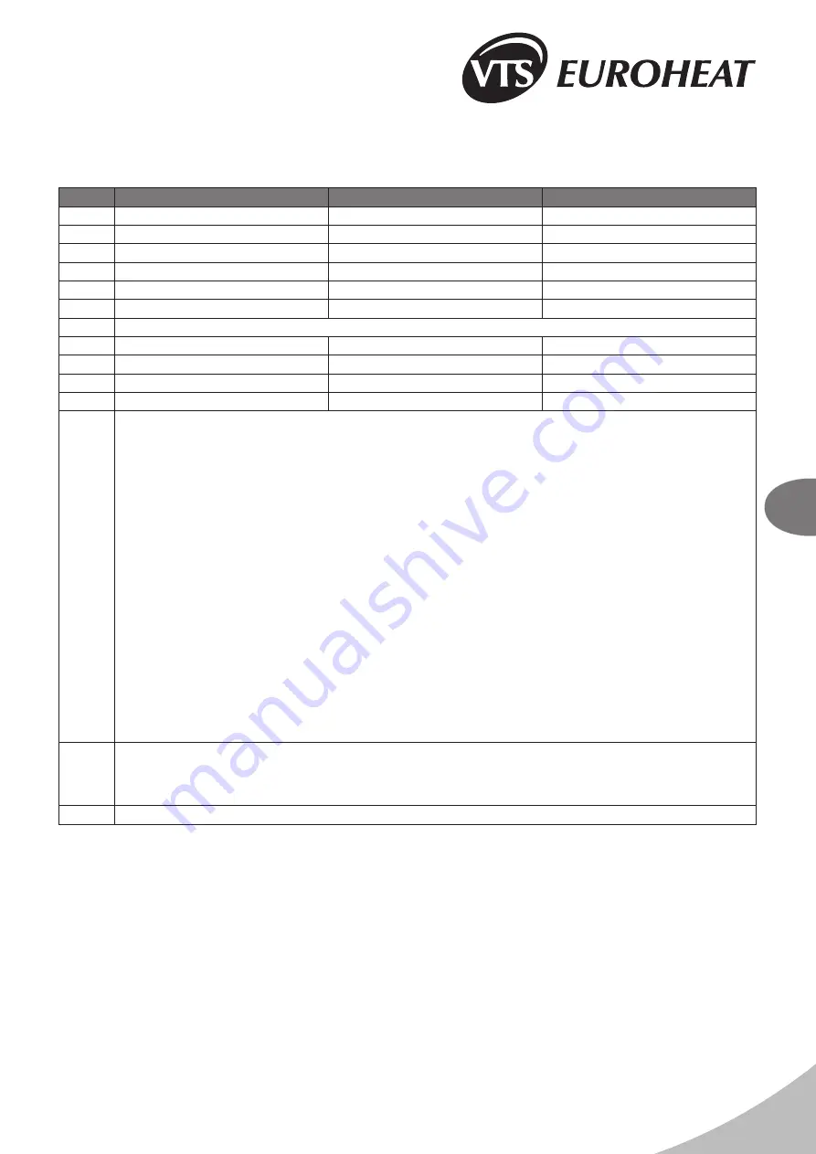
10. TECHNICAL INFORMATION TO THE REGULATION (EU) NO 

327/2011 IMPLEMENTING DIRECTIVE 2009/125/EC

DR 100

DR 150

DR 200

1. 

26,0%

26,0%

26,0%

2. 

B

B

B

3. 

Total

Total

Total

4. 

21

21

21

5. 

VSD-No

VSD-No

VSD-No

6. 

2014

2014

2014

7. 

VTS Plant Sp. z o.o., CRN 0000144190, Poland

8. 

1-2-2801-0232

1-2-2801-0233

1-2-2801-0234

9. 

0,68kW, 6182m³/h, 128Pa

0,516kW, 4239m³/h, 124Pa

0,68kW, 6182m³/h, 128Pa

10. 

1372RPM

1370RPM

1372RPM

11. 

1,0

1,0

1,0

12. 

Disassembly of the machine must be carried out and/or supervised by qualified personnel with appropriate expert 

knowledge.

Contact a certified waste disposal organization in your vicinity. Clarify what is expected in terms of the quality of 

dismantling the machine and provision of the components.

Dismantle the machine using the general procedures commonly used in mechanical engineering.

WARNING

Machine parts can fall The machine is made up of heavy parts. These parts are liable to fall during dismantling. This can 

result in death, serious injury, or material damage.

Follow the safety rules:

1. Disconnect all electrical connections.

2. Prevent reconnection.

3. Make sure that the equipment is at zero voltage.

4. Cover or isolate nearby components that are still live.

To energize the system, apply the measures in reverse order.

Components:

The machines consist for the most part of steel and various proportions of copper, aluminum and plastics (Impeller made 

of SAN - styrene, acrylonitryle, construction material with 20% glass fiber) and rubber-neoprene (seat of bearings/hub). 

Metals are generally considered to be unlimitedly recyclable.

Sort the components for recycling according to whether they are:

Iron and steel, aluminum, non-ferrous metal, e.g. windings (the winding insulation is incinerated during copper recycling), 

insulating materials, cables and wires, electronic waste (capacitor ect.), plastic parts (impeller, winding cover ect.), 

rubber parts (neoprene). The same goes for cloths and cleaning substances which have been used while working on the 

machine.

Dispose of the separated components according to local regulations or via a specialist disposal company.

13. 

Long failure-free operation depends on keeping the product/device/fan within performance limitations described by 

selection software or maintenance manual.

For proper operation, read carefully maintenance manual, with special attention on “installation”, “start-up”, and 

“maintenance” chapters.

14. 

fan casing, internal profiles

Summary of Contents for DEFENDER 100 EHN

Page 1: ...EN Technical documentation DEFENDER 100 200 WHN DEFENDER 100 200 EHN DR ver 1 9 07 2014 Check us on...

Page 2: ...DEFENDER 100 200 WHN DEFENDER 100 200 EHN...

Page 3: ...E 6 SERVICING 6 1 PROCEDURE IN CASE OF DEFECTS 6 2 COMPLAINT PROCEDURE 7 INDUSTRIAL SAFETY INSTRUCTION 8 TECHNICAL DATA 8 1 WATER AIR CURTAIN DEFENDER 100 200 WHN 8 2 ELECTRIC AIR CURTAIN DEFENDER 100...

Page 4: ...after the completion of the assembly Prior to the commencing of any installation or maintenance work it is required to disconnect power supply and protect it against unintentional activation 2 STRUCT...

Page 5: ...n air capacities up to 5000 m3 h The control of the electric motor as well as thermal protections of the winding has been coupled with the control system which resulted in increasing safety of operati...

Page 6: ...itive effect on curtain operation doors or windows that are constantly open in the room thus creating a draft presence of awning roofs etc on the outer side of the door constant and open access to sta...

Page 7: ...nsists in attaching the installation handles to the unit 1 at regular intervals as in OPTION I In order to do so you should slide 2 DR 1m 3 DR 1 5m or 4 DR 2m assembly screws 2 M10x80 in each of the t...

Page 8: ...In rooms with very high levels of dustiness In rooms with aggressive atmosphere due to the presence of copper and aluminium structural elements in the heat exchanger and electric heaters IMPORTANT The...

Page 9: ...e Connection to the electric system must be performed by a duly authorized and qualified person Wire passes are located on the back side of the curtain 1 control wire packing 2 power wire packing The...

Page 10: ...draining a few litres of water prior to the connecting of hydraulic conduits the supply conduits in particular It is advised to use vent valves in the highest point of the system It is recommended to...

Page 11: ...ice DEFENDER 100 200 WHN EHN Circumstances in which the defect occurred remarks on the bill of lading inventory issue condition of cardboard Should the casing be defective it is required to present ph...

Page 12: ...TRUCTION Special instructions concerning safety IMPORTANT Prior to the commencing of any work related to the device it is required to disconnect the system secure it properly and wait until the fan st...

Page 13: ...0 24 0 20 0 10 0 08 p kPa 2 38 2 04 1 73 1 45 1 73 1 44 1 17 0 93 1 15 0 91 0 69 0 49 0 63 0 43 0 13 0 09 Flow rate of air at 1470 m3 h speed 2 air velocity at the output 7 6 m s noise level 58 dB A...

Page 14: ...14 3 78 3 19 2 65 2 16 2 68 2 17 1 72 1 31 1 7 1 28 0 91 0 59 Parametry DEFENDER 200 WHN Tz Tp C 90 70 80 60 70 50 60 40 Tp1 C 5 10 15 20 5 10 15 20 5 10 15 20 5 10 15 20 Flow rate of air at 4890 m3...

Page 15: ...5 1 30 3 Flow rate of air at 1290 m3 h speed 1 air velocity at the output 6 7 m s noise level 52 dB A Pg kW 3 6 6 0 3 6 6 0 3 6 6 0 3 6 6 0 Tp2 C 12 7 18 4 17 7 23 4 22 7 28 4 27 7 33 4 Parametry DEFE...

Page 16: ...dB A Pg kW 10 8 13 5 10 8 13 5 10 8 13 5 10 8 13 5 Tp2 C 14 2 17 4 19 2 22 4 24 2 27 4 29 2 32 4 Flow rate of air at 2500 m3 h speed 1 air velocity at the output 5 5 m s noise level 54 dB A Pg kW 10 8...

Page 17: ...10 13 5 19 5 19 28 6 0 12 0 13 5 Maximum flow rate m h 1880 3570 4890 2150 3500 5000 Maximum temperature of heating medium C 95 Maximum working pressure MPa 1 6 Water volume dm 0 5 0 85 1 2 Diameter...

Page 18: ...g 27 4 26 9 37 4 36 6 48 4 47 2 25 7 35 4 45 6 Engine IP 20 EN Heating output at the opening of the valve water temperature of 90 C and temperature of inlet air 15 C Heating output in the heating mode...

Page 19: ...he equipment is at zero voltage 4 Cover or isolate nearby components that are still live To energize the system apply the measures in reverse order Components The machines consist for the most part of...

Page 20: ...nting of any cover shut down the electric power at least by disconnecting the main switch Electrical connection of the thermostat door switch valve actuator or control panel is to be carried out befor...

Page 21: ...f installation Place of installation Detailed description of defect Contact person Name and surname Telephone E mail This field must be filled if the complaint notification refers to the following equ...

Reviews: