A08 - 25.09.2015
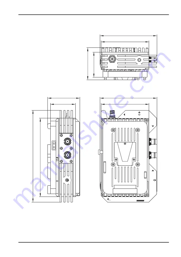
VTQ WMS HD - V/G-Mount TX
41
48
92
62
110
151
176
Antenna
Fan ON/OFF
SDI IN
SDI OUT
Fan
(Reset)
F
S
VTQ WMS
HD
V-Mount
A3. Technical details
Technical details
Page 1: ...Wireless Monitoring Solution VTQ WMS HD V Mount G Mount Reference guide A08 25 09 2015 VTQ WMS HD V G Mount TX...
Page 2: ...0 3 2 Mounting the transmitter 11 3 3 Power supply 12 3 4 Connectors 14 4 Configuration 4 1 Starting the transmitter 17 4 2 Screen saver 17 4 3 Program selection 18 4 4 Modulation and transmission pow...
Page 3: ...d this reference guide thoroughly in order to both avoid wrong operation and be able to use the hardware in an optimal way Please keep the manual in a safe place for future references Manufacturer VTQ...
Page 4: ...ure reference Warning Warnings give information which if strictly observed will prevent personal injury or death or damage to personal property or the environment They are boxed and shaded for emphasi...
Page 5: ...hock In case liquids or similar substances end up inside the unit please immediately disconnect the voltage supply and contact the manufacturer Do not open disassemble or modify the system Incorrect h...
Page 6: ...erfect partnership between VTQ and your business Return of equipment If you need to return equipment for repair please contact your distributor or the manufacturer VTQ Videotronik GmbH Gruene Strasse...
Page 7: ...o signals Main features rugged housing and stable connectors different setups for high picture quality HPQ and extreme transmission ranges HG H 264 compression according to EBU standards small bandwid...
Page 8: ...res made of steel or metal can stop radio waves This also includes fences made of wire steel reinforcement in the masonry or metal coated window panes Leaves from trees or bushes or rain or snow as we...
Page 9: ...s the antenna socket is exposed to a greater leverage when under intense pressure and can be damaged as a result of this Pay attention if possible to the identical altitude of transmission and recepti...
Page 10: ...moving camera work for example in operations with steadycam etc Possible antenna configuration at the receiver antenna 1 vertical 90 antenna 2 horizontal 0 or antenna 1 turned to 45 antenna 2 turned t...
Page 11: ...attention to the quality of the cable and plugs used Example DX cable Aircell 7 Cable attenuation 2 4GHz 0 36dB per metre 5 8GHz 0 65dB per metre Effect on the range at 3dB attenuation range divided b...
Page 12: ...and transmitter with only one battery 3 1 General notes 3 Connectors and control elements Connectors and control elements 10 VTQ WMS HD G Mount VTQ WMS HD V Mount Rear view Front view Antenna Fan ON O...
Page 13: ...emount the battery from the camera 2 Now fit the transmitter as described in the picture above to the mount of your camera and move it until it locks into place 3 Fit the battery to the connection on...
Page 14: ...is here connected to the transmitter It power supplies the transmitter 3 POWER TAP The transmitter is additionally equipped with a 2 pole power tap connection on the side Thus a camera head light may...
Page 15: ...camera is automatically power supplied by the transmitter 2 G MOUNT battery Here an external G Mount battery is to be connected to the transmitter It supplies the transmitter with power Antenna Fan ON...
Page 16: ...lease mind the frequency of the antenna it has to match the frequency range of the transmitter Do use the transmitter with attached antenna only Never switch on the transmitter without connecting an a...
Page 17: ...contains a lot of noise this produces huge data rates in the encoder In cases of extreme noise levels in the original video signal the resulting data rate can increase to such an amount that the remai...
Page 18: ...are of a sufficient circulation of air to avoid overheating of transmitter We recommend to switch of the fan in case of need for a short time only 7 Control panel and display The transmitter comes wit...
Page 19: ...ceiver has been established During this start up process occasional picture flickering or frame drops are possible If the transmitter does not auto detect a new video format after this has been change...
Page 20: ...If you change the transmitter program you have to adjust the receiver to the same program channel 1 4 Configuration Configuration 2 4GHz 2205 0 2220 0 2240 0 2260 0 2280 0 2300 0 2320 0 2340 0 2360 0...
Page 21: ...lity This settings uses the 16QAM modulation which transfers a higher data rate per second yet consequently is more susceptible to transmission interferences and errors Please note that setting 16QAM...
Page 22: ...s saved automatically The following settings are available depending on the status of your model HG or HPQ HG low Modulation QPSK Transmission power 10mW HPQ low Modulation 16QAM Transmission power 10...
Page 23: ...n request As a result the saved data rate 2MBit leads to an increase of image quality In order to change this setting press the Arrow down button With every keystroke the setting Audio on Audio off ch...
Page 24: ...internal electronics switches off and stops the video transmission In order to be able to restart the transmitter and thus continue the transmission it is inevitable to allow the transmitter a cool do...
Page 25: ...the ARROW UP and ARROW DOWN button Choose a menu item and press the OK button in order to enter the respective menu items Some menu offer the possibility to access further items by pressing the arrow...
Page 26: ...ncel this operation by pressing either the ARROW UP or ARROW DOWN button The message BACK appears in the display Press the OK button to cancel this operation Please press the OK button to reset the tr...
Page 27: ...evice please take the following points into account This test should only be made in LOS conditions the transmitter and receiver must be placed in visibility range to each other There must not be any...
Page 28: ...r wieless sources please do the following Take care that transmitter and receiver are connected correctly Adjust the transmission setting to any low profile HG low or HPQ low Choose an identical chann...
Page 29: ...tween in order to avoid further possible error sources signal converter or distributor Ideally you are able to compare both the clean video source with the receiver output signal in order to come to a...
Page 30: ...oint 6 1 A Distance between TX and RX too large TX RX in proper distance LOS B Are the antennas aligned identically Standard vertical polarisation C Booth receiver tuners displays identical parameters...
Page 31: ...A08 25 09 2015 VTQ WMS HD V G Mount TX 29 Remarks Remarks...
Page 32: ...A08 25 09 2015 VTQ WMS HD V G Mount TX 30 Remarks Remarks...
Page 33: ...A08 25 09 2015 VTQ WMS HD V G Mount TX 31 Remarks Remarks...
Page 34: ...available bit rate The degree of success in almost filling the available space is a measure of the quality and efficiency of the compression system COFDM Coded Orthogonal Frequency Division Multiplex...
Page 35: ...s It is used e g on compact discs CD or for wireless transmissions Guard Interval GI The guard interval is one of the most important parameters for robustness of the COFDM signals It is inserted betwe...
Page 36: ...nal quality MPEG Moving Pictures Experts Group The MPEG is a experts group which standardizes video compression MPEG 2 is a MPEG Standard regarding video and audio data compression Also this standard...
Page 37: ...ubled SDI Serial Digital Interface The SDI Standard describes the transmission of a digital serial video stream The video data is transmitted uncompressed with bit rates from 143 Mbit s NTSC composite...
Page 38: ...pproval and licence free in all member states Please consider the local or regional regulation concerning the transmission power EIRP when installing gain antennas VTQ WMS HD kein ISM Frequency range...
Page 39: ...y Germany Bundesnetzagentur Postfach 8001 53105 Bonn Telefon 0228 14 0 Telefax 0228 14 88 72 E Mail info bnetza de Webseite www bnetza de Swiss Federal Office for Communications Rue de L avenir 44 CH...
Page 40: ...A08 25 09 2015 VTQ WMS HD V G Mount TX 38 Declaration of conformity Conformity Transmitter Series VTQ WMS HD A02 vom 01 09 2015 Dr Steffen Enke Managing Director J rgen Bergner Test Engineer...
Page 41: ...A08 25 09 2015 VTQ WMS HD V G Mount TX 39 Declaration of conformity Conformity Receiver Series VTQ WMS HD A02 vom 01 09 2015 Dr Steffen Enke Managing Director J rgen Bergner Test Engineer...
Page 42: ...A08 25 09 2015 VTQ WMS HD V G Mount TX VTQ WMS HD V Mount 48 92 62 110 151 176 Antenna Fan ON OFF SDI IN SDI OUT Fan Reset F S VTQ WMS HD V Mount 40 A3 Technical details Technical details...
Page 43: ...A08 25 09 2015 VTQ WMS HD V G Mount TX 41 48 92 92 62 110 110 48 62 151 176 Antenna Fan ON OFF SDI IN SDI OUT Fan Reset F S VTQ WMS HD V Mount A3 Technical details Technical details...
Page 44: ...A08 25 09 2015 VTQ WMS HD V G Mount TX VTQ WMS HD G Mount 48 92 65 115 151 176 Antenna Fan ON OFF SDI IN SDI OUT Fan Reset F S VTQ WMS HD G Mount 42 A3 Technical details Technical details...
Page 45: ...A08 25 09 2015 VTQ WMS HD V G Mount TX 43 48 92 92 65 115 115 48 65 151 176 Antenna Fan ON OFF SDI IN SDI OUT Fan Reset F S VTQ WMS HD G Mount A3 Technical details Technical details...
Page 46: ...16QAM Punktierung Codec rate 3 4 Guardintervall Guard interval 1 16 Symboll nge Carriers 2k Bandbreite Bandwidth 8MHz Methode Method H 264 Verz gerung Delay 22ms Enc Dec Videonorm Video standard PAL N...
Page 47: ...hme Power consumption max 12W Temperatur Betrieb Operating temperature 10 C 50 C Temperatur Lagerung Storage temperature 10 C 50 C Abmessungen Dimensions 110 x 176 x 62mm V Mount 115 x 176 x 65mm G Mo...
Page 48: ...e E Mail main vtq de This product was produced under a Management System certified by ISO TS 16949 and DIN EN ISO 9001 2000 If you have any problems when installing the device please do not hesitate t...