Status:
Unit allows all programming functions (Triggers, trigger timing,
Unity gain, input mode, input disable or enable, and input offset)
while unlocked.
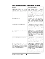
5. User suppresses (or enables) power-on countdown timer indicator (During power-
up only) (Front panel or RS-232 port)
Countdown timer displays number of seconds until ready during power up warmup
sequence.
User input:
During the preamp’s power up cycle, user presses the Mute switch,
or enters command via RS-232 port. Addressable through RS-232
port also – see specific section for command structure.
Indication:
Countdown timer display toggles between display and suppress
display with each press of the Mute button during power on warm-
up cycle. If the countdown is currently displayed Power-on
countdown display is turned off when mute button is pressed, and
countdown display timer is returned if the mute switch is pressed
again during the power-on cycle.
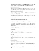
Status:
Power-on countdown mode is turned on and off depending on the
current state. (Remote control mute button does not change the
power-on countdown display.)
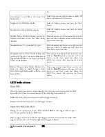
6. User changes trigger output turn-on time (During power-up only) (Front panel or
RS-232 port) (Unlocked mode only)
Triggers are used to remotely power on other components in the system, such as
power amplifiers, which are turned on after the preamplifier is warmed up. Trigger
outputs are typically 12 Volt systems, connected via hardwired connection between
components. Triggers typically perform a hold function: when power is released the
remotely powered component automatically powers down.
User input:
User holds down either of Input 1 or 2 buttons (for trigger 1 or 2).
To set trigger timer, user rotates control knob clockwise to 99
maximum (to increase trigger time) or counter-clockwise to 01
minimum (to decrease trigger time). Rotating volume control
counter-clockwise until numerical display shows OF turns off
selected trigger. Addressable through RS-232 port also – see specific
section for command structure.
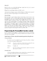
No two triggers can be set for the same turn on time - numerical
display skips already selected trigger times.
Indication:
Except for setup via the RS-232 port, the numeric display changes
from incremental timer count (if not suppressed) to steady numerical
display indicating time at which trigger output will turn on after
power-up cycle is completed. Triggers that are programmed off will
not light trigger LEDs. Trigger outputs that are programmed will
blink input LEDs red during power-up cycle before turning on each
selected trigger. Countdown begins again at 90 seconds after each
TL6.5 Preamplifier Owner’s Manual
VTL
28


