Page 5
Connecting the Peripherals
After mounting the unit, you are ready to connect the peripherals to the unit. For your own safety, please hold the unit steady while connecting the cables. The illustration shows the
back view of the Vista
™
.
1. Identify the power cable and connect one end into the back of the unit and the other end into the wall outlet.
2. Identify the LAN cable and connect one end as shown into the LAN port and the other end your network drop.
3. Install the VGA adapter onto the end of the VGA monitor cable and connect it to the Vista
™
unit as illustrated.
4. Connect one end of the microphone cable to the microphone and the other end into the Microphone-1 port on the back of the unit.
5. Connect the 3.5mm stereo end of the audio cable into the Audio port on the back of the Vista
™
and the RCA (phono) ends to the Audio In connectors at the back of the
monitor.
6. Connect one end of the telephone cable into the Phone Add port and the other end to the telephone wall outlet.
7. Place the four AAA batteries into the RCU.
Quad BRI Connections
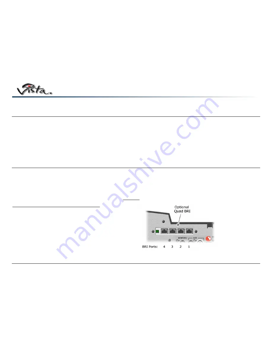
The optional Quad BRI network adapter supports ISDN BRI networks. It requires the S/T interface of a BRI NT1 device in an ISDN network. If your system has the Quad BRI option
installed, follow the instructions below to connect your lines correctly.
Note
: The NT1 interface may be provided by the ISDN service provider.
Connecting BRI Lines to the Quad BRI Network Adapter
You can connect as many as four lines to the Quad BRI card (see illustration). If you use fewer than four lines, connect them to the card in the order described in this table:
Important Note!
The ISDN connections on the Quad BRI adapter are numbered 1 through 4 from
right-to-left
.
Number of BRI lines
Quad BRI card ports used
1 1
2 1
and
2
3
1, 2 and 3
4
1, 2, 3 and 4
Note
: Your ISDN setup is not complete until ISDN DN (Directory Number) and, if
required, SPID (Service Provider ID) settings are configured.


