VQ VQA041B Instruction Manual Download Page 4

2mm

3x20mm screw
 (not included)

Retract pushrod

BOTTOM-VIEW

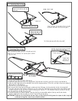
Trial fit the push rod into the wing. Join the pushrod to the retract 
gear arm and trial fit the retract into the wing.

After checking that the retract works 
smoothly, fix the retract on the wing 
with 3x20mm self tapping screws.
Do the same way with other half wing.

5- Retract landing gear installation

Put the nylon ring

Retract push rod

Retract gear arm

Retract pushrod

VQ-AR03 -160223
Retract (option)

VQ-AR03 -160223
Retract (option)

Plywood buffer
included with 
retract set.

FRONT-VIEW

WING-TOP

X

Retract landing gear
servo

4- Servo Installation

TOP VIEW

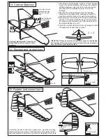
3- Retract servo tray

TOP VIEW

Cut away only
the covering

Note: The head of servo should be positioned 
toward the rear of the wing.

Install the retract servo onto the retract servo mount 
and secure it in place with four screw (included with radio set).

BOTTOM

RETRACT SERVO INSTALLATION

1.5mm

1/16”

B

C

A

CENTER
   WING 
SECTION

CA

CA

CA

CA

BOTTOM

A

B

C

Retract servo tray installation

CENTER
   WING 
SECTION

Retract servo 
mount

Retract servo 
mount

Retract servo tray
1/8(3mm plywood)

Secure one end of the 
aileron extension cord 
with adhesive tape

RETRACT
  SERVO

Summary of Contents for VQA041B

Page 1: ...s not a toy If modified or flow carelessly it could go out of control and cause serious bodily injury or property damage Before flying your airplane ensure the air field is spacious enough Always fly...

Page 2: ...gine 12x6 for 60 4 cycle engine 12x7 for 70 4 cycle engine 13x8 Brushless Motor Silicone tube Extension for aileron servo retract servo 46 50 2 cycle REQUIRED FOR OPERATION Purchase separately Linkage...

Page 3: ...he center line marking sure that the V of the dihedral brace is positioned correctly 7 Do the same way with the other wing half 8 Carefully slide the wing halves together ensuring that they are accura...

Page 4: ...t option Plywood buffer included with retract set FRONT VIEW WING TOP X Retract landing gear servo 4 Servo Installation TOP VIEW 3 Retract servo tray TOP VIEW Cut away only the covering Note The head...

Page 5: ...EW BOTTOM VIEW 3x20mm screw 2x5mm screw 4 8 4mm collar 2 Plastic retainer 2 Plastic retainer Ply gear mount plate x 2 Gear mount x 2 2mm Main landing gear 2mm 3x12mm screw Gear mount 1 3x20mm Nylon ge...

Page 6: ...me way with second aileron servo Switch on the radio trims centered then mount the ailerons servo horn in neutral position The servo horn should be perpendicular to the servo YES NO Hinge Line Control...

Page 7: ...ng the sharp hobby knife carefully cut away the covering inside the lines which were marked above 3 Spread epoxy 30 minute onto the top and bottom of the horizontal stabilizer along the area where the...

Page 8: ...f the vertical stabilizer along the area where the covering was removed and to the fuselage where the vertical stabilizer mounts 4 Install the vertical stabilizer into the fuselage and adust the align...

Page 9: ...ine Four stoke or two stroke engine Throttle servo 2mm screw Throttle pushrod 18 Linkages 2mm screw Elevator servo Elevator pushrod Connector Connector Connector 2 3 Elevator push rod Elevator push ro...

Page 10: ...nce from the prop hub to the fire wall is 121 123mm 4 7 4 8 in 121 123mm Engine thrust on balk head is already adjust at factory 1 5 TOP VIEW Mark the engine mounting plate where the four holes are to...

Page 11: ...the plywood at each of the four marks marked CA 3mm 1 2 Note The aluminum motor mounting included with electric motor set Checking for leaks block the vents and blow into the feed if in doubt submersi...

Page 12: ...nd insert the cowl on to the fuselage so the distance from the fire wall to the front of the cowl is 4 23 32 to 4 55 64 120 to 122mm Remove the cowl from the fuselage and carefully cut the opening for...

Page 13: ...4x35mm bolts to mount the engine would also be long enough to mount the flatform The lead should be permanently glued on with epoxy IMPORTANT Recheck the C G After the weight has been installed Secur...

Page 14: ...VATOR STROKE AILERON STROKE 26 Control Surface 1 3 16 35mm 1 4 6mm 1 4 6mm 3 8 10mm 1 3 16 35mm Adjust the engine always from behind but never from infront or the sides as rotating propeller may badly...

Reviews: