
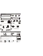

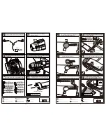


The servos installation finished sketch map.
Assemble the receiver and the battery to appropriate
in the fuselage.
Elevator servo
Rudder servo
Throttle servo
Receiver
Connect the electric retract & receiver as illustration below.
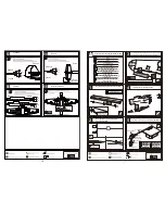
1.5mm
12
Ply(15x15x3mm)
12
TP Screw (2.3x8mm)
1
Canopy
2
Pvc part
2
Washer (3x6mm)
2
2
Screw (3x15mm)
2
Blind Nut (3mm)
4
Ply (17x17x8mm)
2
Plastic tube(5x50mm)
2
Wood dowel (6x30mm)
ply(3mm)
2
1
Location wooden Block (2mm)
2
Wooden Block (9mm)
1
Drop tank
PVC
2
PVC
2
PVC
1
PVC
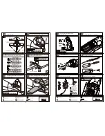
According to the location wooden block and mark in the
cockpit through the holes in the location wooden block.
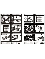
Location wooden Block (2mm)
1
Location wooden Block (2mm)
6
TP Screw (2.3x8mm)
Ply (15x15x3mm)
6
TP Screw (2.3x8mm)
Epoxy the plies under the cowing in fuselage and assemble
the cowing to fuselage with TP screw.
Drim the relevant position on the cowling for
assembling the engine.
64
65
12
66
63
62
Accessory list for the coming installation steps.
Trim the covering carefully from the relevant position
in the wing for assembling the wheel wells.
Assemble the retract to appropriate position in the wing.
Epoxy the wheel wells to the wings.
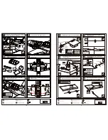
8
TP Screw (3x20mm)(Not included)
Rib template (2mm ply)
6mm
Wood dowel (6x30mm)
4
Wood dowel (6x30mm)
1
Rib template (2mm ply)
1
Main wing joiner (25x750mm)
Main wing joiner (25x750mm)
6mm
Rib template (2mm ply)
2
Screw (6x50mm)
Blind Nut
Screw (6x50mm)
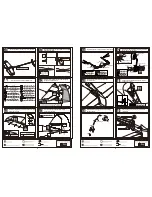
According to the rib template drill holes in one wing and
epoxy wood dowel in them.
According to the rib template drill holes in the fuselage.
Assemble the wings to the fuselage steadily.
Reinforce the connection between the fuselage and
the wings by the screws as illustration.
23
22
27
5
25
24
26


