
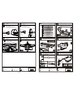

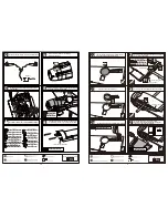


Make sure hinges are
mounted in the same line.
1mm
Rudder
Tailing
edge
Cut away the rubber tube when
the epoxy glue dried.
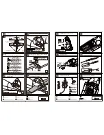
Make sure they are in
the right position while
installing.
Epoxy the fibreglass tubes to appropriate position as
below and leave some space with width of 1mm between
tailing edge and rudder.
Pin hinge(4.7x70mm) 3
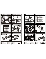
Connect the elevator and the servo via the steel wire.
Elevator servo steel wire
73mm
66mm
26mm
2.5mm
2.5mm
Securely glue together. If coming off during flights, you 'll
lose control of your airplane which leads to accidents!
2
Plastical tube(3x50mm)
30mm
25mm
3mm
110mm
Drill holes to the relevant position in the tailing edge
and epoxy the rudder to them.
Drill holes to appropriate position in the rudder and epoxy
the ping hinges in them
Drill a hole to the appropriate position through
the rudder as illustration.
4
Plastical tube(3x50mm)
4
Steel wire (0.5x3000mm)
2
2
2
Clevis
Washer(3x15mm)
Lock Nut (3mm )
1
Screw (3x80mm)
4
Copper joiner
3
Pin hinge(4.7x70mm)
4
Clevis
4
4
Screw (2x10mm)
Nut (2mm )
4
Washer(2x5mm)
TP Screw(3x20mm)
Washer (3x6mm)
4
4
1
1
1
Wooden Block (9mm Ply)
Wooden Block (3mm Ply)
6
TP Screw (2.3x8mm)
Ply (15x15x3mm)
6
Wheel (45mm)
40
39
41
42
43
8
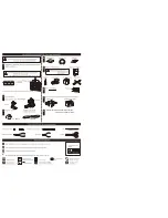
Accessory list for the coming installation steps.
2
Steel wire (0.5x3000mm)
2
2
2
Clevis
Washer(3x15mm)
Lock Nut (3mm )
1
Screw (3x80mm)
2
Copper joiner
Washer(3x15mm)
Screw (3x80mm)
Lock Nut (3mm )
Clevis
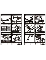
Aluminum tube
Steel wire
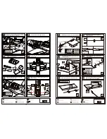
The sketch map after the rudder shaft assemble finished.
The sketch map of the linkage for the rudder
and the tail wheel.
Collar
Tail landing gear
Collar
Collar
Assemble the tail landing gear to the wheel steeling
mounts as below.
Wooden Block (9mm Ply)
Wooden Block (3mm Ply)
TP Screw(3x20mm)
Washer (3x6mm)
TP Screw(3x20mm)
Washer (3x6mm)
4
4
1
1
Wooden Block (9mm Ply)
Wooden Block (3mm Ply)
Wooden Block (9mm Ply)
Wooden Block (3mm Ply)
Assemble the wheel mount to the thick wooden block
with screw,cut the surplus parts and epoxy the thinner
wooden block to it as illustration.
2
Steel wire (0.5x3000mm)
Steel wire (0.5x3000mm)
Wire for rudder servo
Wire for elevator servo
Wires for tail wheel
Wheel (45mm)
The scatch map of the servo wires position inside
the fuselage.
Epoxy the whole wheel mount set to the form in the
fuselage and be carefule don't let the arm touch the
fuselage when it works
45
46
47
48
49
9
44


