Manual DINAMO Plug & Play
Control your miniature world
Page 24 of 32
Version 1.2 – Dec 21
st
, 2017
2017 Leon van Perlo
Address S1
S2
S3
S4
Address S1
S2
S3
S4
0 On
On
On
On
8 On
On
On
Off
1 Off
On
On
On
9 Off
On
On
Off
2 On
Off
On
On
10 On
Off
On
Off
3 Off
Off
On
On
11 Off
Off
On
Off
4 On
On
Off
On
12 On
On
Off
Off
5 Off
On
Off
On
13 Off
On
Off
Off
6 On
Off
Off
On
14 On
Off
Off
Off
7 Off
Off
Off
On
15 Off
Off
Off
Off
Table 3: OC32 Addressing
As is the case with the TM44, mind that your control software may offset all addresses
+1.
5.3.4
Changing Addresses
Be aware that if you change the DIPswitch settings on your TM44 and/or OC32/NG modules
while the modules are powered-on, changes will have no effect at that time. DIPswitches are
only read by the modules at boot-time. Therefore in order to read the new address (and for
TM44, the maser/slave setting), your TM44 and OC32/NG modules need to be rebooted
(power-off - power-on).
Changing addresses in a live Dinamo P&P network would not work anyway and could lead to
very strange behaviour. If you read and understand section 6 of this manual you will know
why. To prevent these errors from happening, al modules store their address at boot-time
in memory.
Control your miniature world
Manual DINAMO Plug & Play
2017 Leon van Perlo
Version 1.2 – Dec 21
st
, 2017
Page 9 of 32
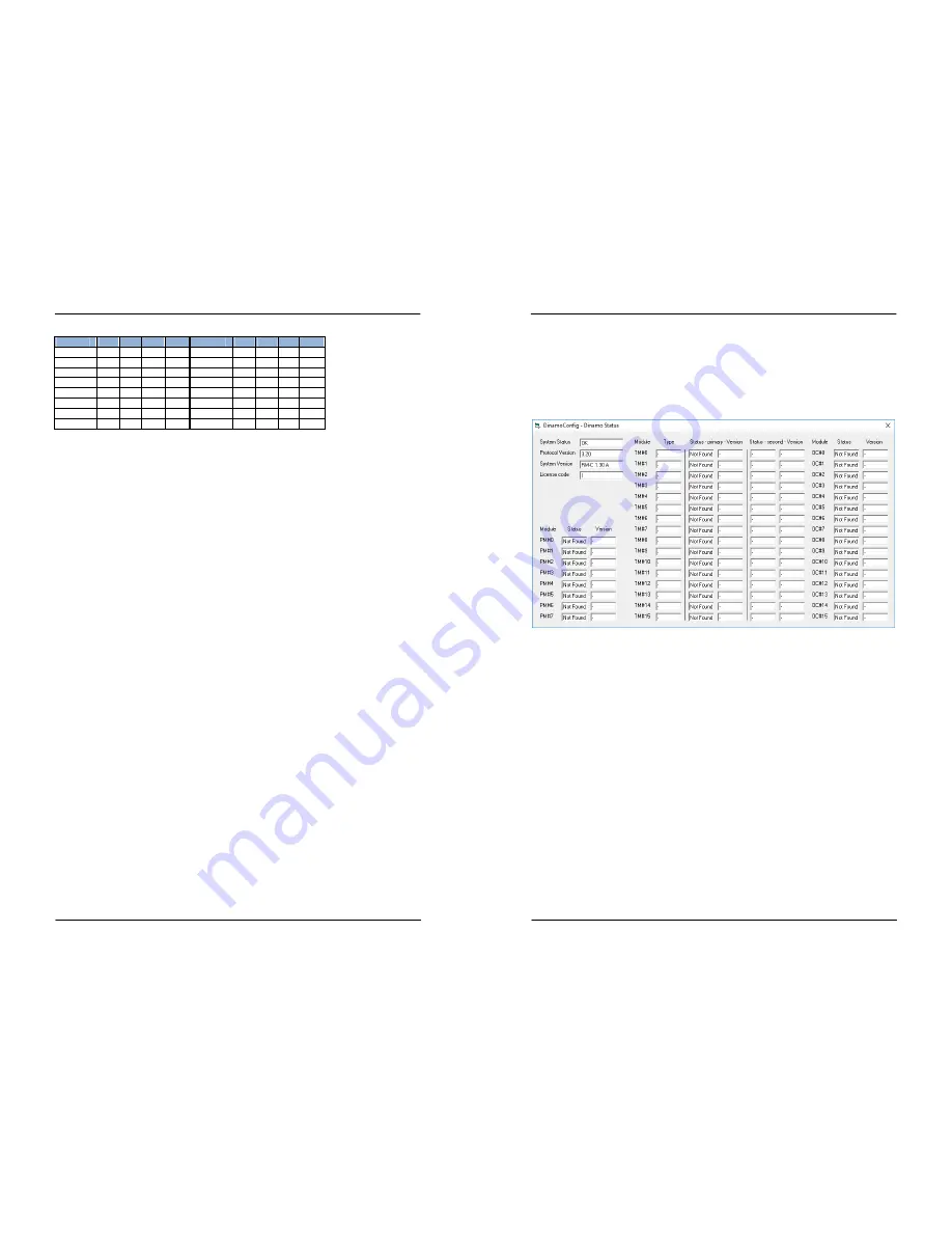
Select the correct com-port and click “Status”. A window similar to the one in fig 7 will
show. Because you have connected nothing else to your RM-C so far, the status of all
modules will show “Not Found”. In the top/left-hand corner you’ll find the “Protocol Version”
and “System Version” of your RM-C. This indicates your PC and RM-C can communicate.
If “System Version” shows an older version than 1.30A, update the firmware of your
RM-C, otherwise a large part of this manual does not apply to your system.
Fig 7: DinamoConfig Status Window
If “System Status” shows “Fault”, there is no reason (yet) to be worried. This is part of
“normal behaviour”.
At this point, notice the LEDs on your RM-C:
•
The blue LED should be lit to show you have USB connectivity.
•
The yellow Tx1 LED is flashing quickly to indicate that the RM-C is transmitting on the
RS485 bus, but it does not find anything since you have not connected any modules yet.
•
The orange LED is flashing quickly to indicate the RM-C is actually interchanging
messages with the DinamoConfig program on your PC. Messages are empty, but are
send back and forth between the two systems to indicate all is well (or not so well in
some cases).
•
The green LED indicates that the RM-C is processing a command from the PC. To see
this, you can press the “Status” button in the main window while watching the LEDs on
your RM-C. You should see the green LED lit briefly, indicating the “Status” command is
processed (actually being some 45 commands al together being executed).
While the orange LED is lit or flashing, do not disconnect your USB interface, since this will
cause the virtual com-port to disappear while it is in use by the DinamoConfig program. If
you want to disconnect USB, you need to stop communication first. In DinamoConfig this
can be done by pressing the “Refresh” button in the main window. This will actually refresh
the list of com-ports available, but the side-effect is that the active com-port is closed.
Now press the “Refresh” button and see the orange LED go off. Wait (at least) 5 seconds
and press “Status”. You will see the window of fig 7, however “System Status” will show


