

128-6832
5 of 16
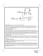
GREY w/ BLACK: Negative Shutdown Input 2
Any time the Grey w/Black wire is grounded, the Remote Start system will stop operating, even if the signal is
received from the transmitter.If the brake light switch in the vehicle switches ground to the brake light circuit,
connect the Grey w/ Black trace wire to the output of the brake light switch. If the brake light switch in the vehicle
sw12 Volts, do not use the Grey w/ Black wire; see Brown w/ Red wire.
BROWN Wire: Positive Shutdown Input 1
Any time +12 Volts is applied to the Brown wire, the Remote Start system will stop operating, even if the signal is
received from the transmitter.If the vehicle has a factory installed hood pin switch, and that switch pr12
Volts to a light under the hood, the Brown wire can be connected to the existing pin switch.
BROWN w/ RED Wire: Positive Brake Input
Any time +12 Volts is applied to the Brown w/ Red wire, the Remote Start system will stop operating, even if the
signal is received from the transmitter. If the brake light switch in the vehicle sw12 Volts to the brake light
circuit, connect the Brown w/ Red wire to the output of the brake light switch. If the brake light switch in the vehicle
switches ground, do not use the Brown w/ Red wire; see Grey w/ Black wire.
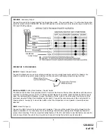
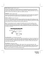
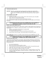
Note: The Brown/Red wire is used for programming, if the brake switch in the vehicle switches ground, a
normally open push-button switch must be added. During the program sequence, when the brake pedal is
pressed and released, this switch will be used in it's place. If the installation of this switch is necessary, connect
one end of the normally open push button switch to the Brown/Red wire, and connect the other end of the switch
to a fused +12 volt source.
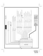
Brake Switch Positive Shutdown Detail
YELLOW w/ BLACK: + 12 Volt Alarm By - Pass Output
This wire provides a 500mA +12 Volt transistorized output when the ignition key is turned to the ON position, and
0 Volts when the ignition key is OFF and when the vehicle is running under the control of the Remote Start. This
wire should be connected to the ignition input of the alarm system. The Yellow w/ Black wire output will allow you
to remote start the vehicle while leaving the alarm armed, and to lock/unlock the doors while running under
control of the remote start system.
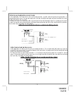
(2) WHITE Wires: Parking Light Output
These wires are the COMMON and NORMALLY OPEN contacts of the on-board parking light relay. If the
vehicle's parking lights are a +12 volt switched system, connect (1) of the White wires to a fused (15A max.) +12
volt battery source, and connect the second White wire to the vehicle's parking light wire. If the vehicle's parking
lights are a chassis ground switched system, connect (1) of the White wires to a chassis ground source, and
connect the second White wire to the vehicle's parking light wire.
5
RED
Summary of Contents for CA-510
Page 14: ...128 6832 14 of 16 13...
Page 15: ...128 6832 15 of 16...


