128-6832
15 of 16
Page 1: ...device must accept any interference received including any interference that may cause undesired operation Warning Changes or modifications not expressly approved by the party responsible for complia...
Page 2: ...insure the drill will not penetrate any existing factory wiring or fluid lines Drill a 1 4 hole in the desired location and thread the pin switch into it If using the mounting bracket first secure th...
Page 3: ...he Red Violet wire above Most vehicles have more than one battery source supplying power to the ignition switch Separate feed wires must be used for the Red and Red Violet wires If your vehicle does n...
Page 4: ...und the CA 410 Remote Start Module is operative When the Black w White wire is open the remote starter is disabled Connect the Black w White wire to one of the wires from the back of the previously mo...
Page 5: ...or programming if the brake switch in the vehicle switches ground a normally open push button switch must be added During the program sequence when the brake pedal is pressedand released this switch w...
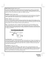
Page 6: ...venting the shock sensor s operation until the Remote Start system shuts off 2 Ignition 3 Output Some newer vehicles use a third ignition wire which is required to start and keep the vehicle s engine...
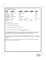
Page 7: ...the Remote Start system engages Blue Pulsed Ground Output After Start The Blue wire will provide a 1 second 300ma pulsed ground output after the vehicle is started under control of the Remote Start s...
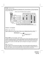
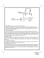
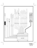
Page 8: ...For Wiring Detail 3 Wire Ground Switched Door Lock Unlock Wiring Detail 8 3 Wire Positive Switched Door Locks In this application the Green wire of the two pin harness provides a 12 volt pulse during...
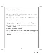
Page 9: ...es 3 Immediately turn the ignition key OFF then back to ON 4 Press and release the program switch 2 times wait 1 second then go to step 5 5 Use the UNLOCK Button to advance to the feature that you wan...
Page 10: ...me to advance to channel 2 The lights will flash 2 times and the dash mounted LED will Flash 2 times indicating that the unit is ready to accept programming for channel 2 which is only used for the un...
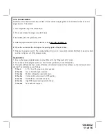
Page 11: ...seconds to indicate that the tach signal is stored and the unit is now out of the program mode DIAGNOSTICS 1 Be sure that programmable feature number 6 is set to the Diagnostics On mode 2 Press and h...
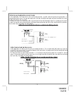
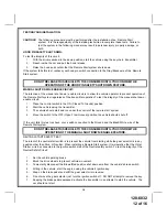
Page 12: ...on 2 Start the vehicle using the transmitter 3 The vehicle should start and run under the control of the remote start system 4 Move the switch to the OFF Open From Ground position the vehicle should s...
Page 13: ...it in place with cable ties or screws Be certain that the mounting location will not inhibit any of the controls of the vehicle 3 Securely tie all wiring up and away from all hot and moving parts that...
Page 14: ...128 6832 14 of 16 13...
Page 15: ...128 6832 15 of 16...