14
Drain connection
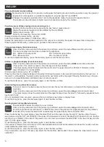
Drainage exhaust holes (Fig.5)
For the proper functioning of the heat exchanger, it is therefore necessary to connect a condensate drain to the hydraulic
system (exhaust) of the house. In addition, to enable the correct outflow of the condensate water, and avoid air eddies, the
condensate drain must always be provided with a siphon (one provided and one at customer’s charge);
To install the exhaust condensation adhere to the following standards:
- give a slope of at least 2% to the exhaust pipe;
- provide for the possibility to disconnect the drain pipe for maintenance (in particular in the case of ceiling installation);
- make sure that the discharge end of the tube is at least below the water level of the siphon;
- make sure that the siphon is always full of water.
Install the drainage exhaust siphon on the unit ejection to avoid unpleasant odors in ambient air.
Areaulic Connections
Ducts used for conveying air must be of the correct size. Ducts (to the outdoors and from the outdoors) must be thermally
insulated and not subject to vibration. The 160 mm standard diameter inlet and outlet ducts must be secured to the
corresponding spigots of the appliance utilizing of clips or other suitable fastening systems.
In case of connecting to the roof:
- the Stale air outlet duct;
- or, the Fresh air intake duct;
You have to use tools and solutions to avoid condensate and the entry of rain water .
We recommend installing at least 500mm of flexible tubing to avoid dragging the vibration or noise caused by installation.
Electrical connections
- Equipment must be powered by f an external electrical power supply.
- Before starting any electrical connection , please check that there is not power to the unit.
- After a few minutes from the first start of the machine , please check that the terminal block screws are still tight.
Wiring diagram (Fig. 6)
Accessories
The appliance can be also equipped with the following optional accessories:
Remote display TAL
(Cod.21.602)
Remote control panel with LCD display for installation inside electrical box 503 . The interface , functions and buttons are
not different from the ones installed on the unit.
For functioning , connection etc.... please refer to the manual supplied with the Remote display.
Dispay remoto TNF
(Cod.21.603)
Remote control panel with touch controls , colours , LCD display that can be wall mounted or built-in wall
For functioning , connection etc.... please refer to the manual supplied with the Remote display. It is possible to order the
built-in wall box for the remote panel TNF with code (SI TNF - Cod. 21.604)
Floor mounting feet MP
(Cod.21.605)
Set of 4 insulated anti-vibration feet for floor mounting. For installation please refer to the manual supplied with the acces-
sory.
Filters kit FDR4
(Cod.21.606)
N° 2 filters with class F7 (ISO 16890 class: ePM1 - 70% efficiency) that can be ordered as a replace for the ones equip
ped with the unit.
ENGLISH
Summary of Contents for VORT HR 550 AVEL
Page 1: ...VORT HR 550 AVEL Libretto istruzioni Instructions Booklet COD 5 571 084 131 12 12 2018...
Page 21: ...21 FIGURE A C B D A 1 2 3 OK 4 5...
Page 22: ...22 7 8 6...
Page 24: ...24 Note...
Page 25: ...25...


