background image

Section 5  -  Memory Functions and Settings

5.1    Saving Traces

When required trace is displayed press      trace will be 
automatically stored with time, date, vp, impedance (z), range 
and cursor position. The trace number that has been saved will 
be shown in the bottom right of the display.

5.2    Recall Trace from Memory

From menu, use keys      and       to scroll to      , press select, 
first saved trace will be displayed, press keys      or     to view 
saved traces. press        to return to menu.

5.3    Trace Comparisons

from menu, use keys     or      to scroll to      , press select, first 
saved trace will be displayed, press keys      or      to select 
required trace. press  Select  to start a new trace, the retrieved 
trace will remain on the display but will be shown as a dotted 
line. the trace from the cable under test will be displayed as a 
solid line

5.4    Delete Saved Traces from Memory

When using this function ensure traces that are to be saved 
have been downloaded to the PC. Once traces have been 
deleted they cannot be retrieved.


From menu, use keys      or       to scroll to     , press Select, 
press       to 'delete all saved'. Press select, to continue with 
deletion follow the instructions displayed

18

Summary of Contents for RapidTrace 1200

Page 1: ...RapidTrace 1200 User Guide Issue 1 0 ...

Page 2: ...ck 10 3 7 Set Velocity of Propergation 11 3 8 Set Cable Impedance 11 3 9 Backlight 11 Section 4 Using the RapidTrace 1200 4 0 Attaching Cable 13 4 1 Testing a cable 14 4 2 Selecting range scales 14 4 3 Single shot and Continuous scan mode 14 4 4 Tone generator 15 4 5 Typical fault displays 16 4 6 Typical Cable Vp Impedance values 16 4 7 How to determine Vp Settings 16 4 8 Variable Gain 17 Section ...

Page 3: ...CONTENTS 3 5 5 Download and Upload Functions 19 Section 6 Maintenance 6 1 Battery replacement 20 6 2 Cleaning 20 6 3 Storage 20 Section 7 Warranty Repair 7 1 Contacting us 21 ...

Page 4: ...ned for use on de energized circuits only Connection to line voltages will damage the instrument and could be hazardous to the operator This instrument is protected against connection to telecom network voltages according to EN61326 1 International Electrical Symbols This symbol signifies that the instrument is protected by double or reinforced insulation Use only specified replacement parts when ...

Page 5: ...tified Using pre determined gain and pulse width and with only 5 control buttons all major operating and setting parameters can be easily accessed A 6km cable run can be scanned in seconds allowing the operator a view of this cable run yet arriving quickly to the fault By using the scan lock facility the cable can be continuously scanned for the location of intermittent faults or the trace held fo...

Page 6: ...play 3 Cursor left decrease setting 4 Cursor right increase setting 5 Store trace select 6 Scan lock Cursor down 7 Range Return 8 Back Light On Off 9 Power on off 10 Gain Control 1 2 1 Features RapidTrace 1200 4 5 9 3 6 8 2 7 6 V1 0 RapidTrace 1200 10 ...

Page 7: ...th range Scan Rate 2 scans second or scan held Memory Caoacity 50Traces Tone Generator 810 1100Hz Battery Life 60 hours continuous scanning Power Supply 6 volts 4 x 1 5AAAlkaline cells Power Down Selectable 1 2 3 minutes or disabled Back Lit Display 128 x 64 pixel Voltage Protection 250 voltsAC OperatingTemp 10º 50ºC StorageTemp 20º 70ºC Dimensions 165 x 90 x 37 6 5 x 3 5 x 1 5 ins Weight 350 gms ...

Page 8: ...core cable including power cable and is lower when a cable is tightly wound on a drum than when installed Section 3 First Operation 3 1 Preparing the RapidTrace 1200 for use Press button to power the tester the following screen will be displayed 1 Model 2 Software version programmed into tester 3 Time Date 4 Battery condition indicator all black battery fully charged as charge decreases symbol cha...

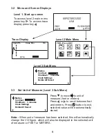
Page 9: ...R Press KEY 3 3 Set Unit of Measure Level 3 Sub Menu Press to move to unit of measure feet or meters Press or to scroll between feet and meters Press button to exit selected value will be automatically stored Note When unit of measure has been selected this will automatically change the V 2 figure which will also be displayed in the selected unit of measure i e FEET or METERS Metres Contrast Shutd...

Page 10: ... setting is displayed press to move to next position When all settings are completed press to return to sub menu settings will automatically be stored 3 5 Set Auto Shutdown Level 3 Sub Menu Metres Contrast Shutdown 3 minutes Clock Settings Delete All Saved To preserve battery life the RapidTrace 1200 is fitted with an auto shutdown feature Shutdown time is selectable between disabled 1 minute 2 mi...

Page 11: ...e the speed is displayed in feet or meters will be determined by the setting selected in section 3 4 From Level 2 Menu using or move to icon Press Select The following sub menu will be displayed Vp 67 Vp Vc Velocity Propergation 3 8 Set Cable Impedance From Level 2 Main Menu press or move to icon Press Select Press or to select required value Press to Escape Values will be automatically stored 3 9...

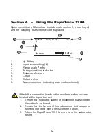
Page 12: ...r 5 Distance of cursor 6 Cursor 7 Output pulse 8 Scan mode icon indicating scan mode selected 1 6 2 3 5 8 4 7 12 Attach the connection leads to the two 4mm saftey sockets located at the top of the unit 1 Ensure that no power supply or equipment is attached to the cable to be tested 2 Ensure that the far end of the cable under test is open or shorted not fitted with a resistive termination 3 Attach...

Page 13: ...and the black clip to the shield screen Shielded Cable Connect the red clip to a wire adjacent to the shield and the black clip to the shield Twisted Pair Separate out one pair and connect the red and black clips to the two wires of the pair Multicore Cable Connect the clips to any two wires Vp 67 Coax 75 7m 0 4m W 13 ...

Page 14: ... distance to the event Position the cursor at the beginning of the event and read off the distance at the bottom left corner On the fault display shown above a low impedance fault occurs at 64 meters shown by a negative spike and a high impedance at 129 meters The open end of the cable is shown as a large positive spike this is used to determine the end of the cable run and the overall length of t...

Page 15: ...lso be used as a tone generator to trace and identify cables and wires The user will need a conventional inductive tone probe within the range 810 Hz to 1110Hz To select tone generator Level 2 From level 2 main menu using or to move to icon press select The tester is now in tone generator mode Upon completion of testing press to return to menu RapidTrace 1200 When tone has been selected connect te...

Page 16: ... Coax Air 98 50 75 T Pair PTFE 71 100 Coax Air Space 94 50 75 T Pair PVC 58 100 Coax Foam PE 82 50 75 T Pair Paper 72nF 88 100 Coax Solid PE 67 50 75 T Pair Paper 83nF 72 100 4 7 How to determine Vp settings If the TDR RapidTrace 1200 is to be used with a cable type for which the Vp is unknown this must first be determined 1 Take a sample of the cable at least 100m or 300ft long 2 Measure the actu...

Page 17: ...e Gain Control To operate user variable gain press and hold down gain control key and press and keys to increase or decrease gain Gain value selected is displayed in the bottom right hand corner of the display 17 ...

Page 18: ...ce Comparisons from menu use keys or to scroll to press select first saved trace will be displayed press keys or to select required trace press Select to start a new trace the retrieved trace will remain on the display but will be shown as a dotted line the trace from the cable under test will be displayed as a solid line 5 4 Delete Saved Traces from Memory When using this function ensure traces t...

Page 19: ...nd Upload Function For operating instructions on using this function refer to the Tracextra software manual The software manual is published on this CD tracextra for bi the software manual is published on this cd 19 ...

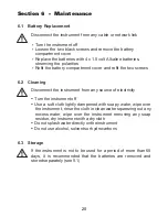
Page 20: ...Turn the instrument off Use a soft cloth lightly dampened with soapy water wipe over the instrument rinse the cloth in clean water squeezing out any excess water wipe over the instrument removing any soap residue dry instrument with a dry cloth Do not splash water directly on the instrument Do not use alcohol solvents or hydrocarbons Disconnect the instrument from any source of electricity 6 3 Sto...

Page 21: ...d qualified personnel New instruments are guaranteed against breakdown due to manufacturing or component defects for 36 months after the purchase date by the user Note Any unauthorized prior repair or adjustment to the instrument will automatically invalidate the warranty 7 1 Contacting Us Vonaq Ltd 1st Floor 9 Greenhill Crescent Watford Business Park Watford WD18 8QU Tel 44 0 1923 242114 Fax 44 0...

Page 22: ......

Reviews: