


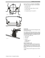


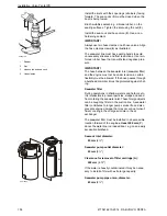


Adjustable engine mount basic position must be cen-
tered in the attachment plate holes. The attachment
plates have oblong holes for adjustment.
Nominal height (
H
):
116 mm ±8 mm
(4.6" ±0.3)
Hole width (
V
):
7 mm
(0.3")
IMPORTANT!
The measurement between the engine mount and the
lower edge of the center adjuster nut (
A
) must never
exceed
20 mm
(0.8"). If this occurs, the threads may
strip.
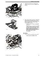
Propulsion Unit
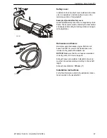
Connecting the drive shaft
1
Install the drive shaft coupling from the engine to
the drive unit by pulling it out and fitting the four
bolts and washers to the drive unit shaft.
2
Check the flange-to-flange drive shaft distance as
illustrated. The length of the shaft should be
370
±15 mm
(15"±0.6). Adjust the engine as neces-
sary.
NOTICE!
If a longer drive shaft is to be used, refer
to
General page 96
.
IMPORTANT!
Check the direction of the two spline coupling
arrows (
1
). The illustration shows the correct posi-
tion: the arrows point toward each other.
If the spline coupling is incorrectly installed there
is a great risk of vibration problems!
3
Tighten the bolts to
70–80 Nm
(52–60 lbf.ft).
p0005969
H
V
p0005972
A
P0010524
1
Installation, Volvo Penta IPS
94
47704162 10-2014 © AB VOLVO PENTA
Summary of Contents for IPS650
Page 1: ...IPS 2 IPS650 IPS800 IPS950 Installation 1 1 E ...
Page 2: ......
Page 156: ......
Page 160: ...47704162 English 10 2014 ...


