background image

General information

9

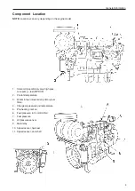
Component Location

NOTE:

 Locations can vary, depending on the engine model.

1.

Solenoid proportional valve, high pres-
sure pump – fuel (MPROP)

2.

Coolant temperature

3.

Water in fuel (mounted on primary fuel
filter).

4.

Charge air pressure and temperature

5.

Pre-heating, inlet air

6.

Fuel pressure, in Common Rail

7.

Fuel pressure

8.

Oil pressure sensor

9.

Main relay

10. Speed sensor, flywheel

11. Speed sensor, camshaft

Summary of Contents for TAD734GE

Page 1: ...EMS 2 Industrial engines TAD734GE Installation 1 1 I ...

Page 2: ......

Page 3: ... 11 Wiringdiagram CIU 12 WiringdiagramDCU 13 CIU 14 General 14 Connection 15 Warning and indication lamps 16 Instruments Easy Link optional 17 Instruments analogue optional 18 Other matters 19 Contents DCU 20 General 20 Connection 21 Parametersettings 22 Connection of VODIA parameter tool 22 Function VODIA 22 Adjustableparameters 23 Engineprotector 24 Enginespeedregulator adjustment 25 Frequency c...

Page 4: ...r the engine in question for relevant information as required espe cially concerning information about safety and running the engine The work must be performed by a Volvo Penta work shop or other authorized well equipped workshop by qualified and experienced personnel Important The following special warning symbols can be found in this manual and on the engine WARNING Warns for the risk of persona...

Page 5: ...sion with resulting dam age Do not change the battery connections when you try to start the engine risk for sparks and do not lean over the batteries Refer to the instructions in the engine operators manual Make sure that the positive and negative battery cables are correctly connected to the corresponding battery terminals You can cause serious damage to the electrical equipment if the cables are...

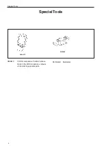
Page 6: ...4 SpecialTools 3838619 VODIA complete with cable harness Refer to the VODIA operators manual whenorderingseparateparts 3838619 9510060 9510060 8 Multimeter Special Tools ...

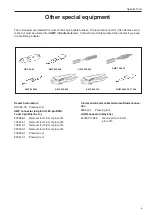
Page 7: ...Quality Action Center if you have trouble finding a dealer Deutschconnectors HDT 48 00 Pressing tool AMP connector 42 pin CIU 62 pin EMS 2 and 3 pin Bosch etc 539968 1 Removal tool 1 5 mm pin width 726534 1 Removal tool 1 6 mm pin width 726519 1 Removal tool 2 8 mm pin width 929039 1 Removal tool 2 8 mm pin width 239635 1 Pressing tool 825514 1 Pressing tool 4 8 mm and 6 3 mm cable terminals Blade...

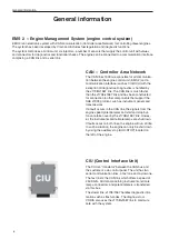
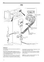
Page 8: ...587 link and has been constructed for connection to other components that support the SAE J1939 protocol such as instrument panels and transmissions If a fault occurs in the CAN link the signals from the engine speed potentiometer and start and stop but tons are taken over by the J1708 J1587 link Howev er the instruments and tell tale lamps are shut down If faults occur on both links the engine wi...

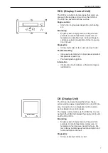
Page 9: ... limits for oil temperature coolant temperature speed drop Pre heating before ignition Information Information about hardware software and engine identification DU Display Unit The DU is an instrument panel that shows the en gine s working values in graphical form on an LCD dis play It consists of an computerized unit for perma nent installation in a control panel The display communicates via the ...

Page 10: ...s closed when the fuel valve is closed fuel is injected into the cylin der The parameters that determine the volume of fuel injected are Requested engine speed Engine protection functions The temperature Charge air pressure High altitude adjustment The control unit contains an air pressure sensor and high altitude compensation for engines operating at high altitudes The function limits the fuel vo...

Page 11: ...oportional valve high pres sure pump fuel MPROP 2 Coolant temperature 3 Water in fuel mounted on primary fuel filter 4 Charge air pressure and temperature 5 Pre heating inlet air 6 Fuel pressure in Common Rail 7 Fuel pressure 8 Oil pressure sensor 9 Main relay 10 Speed sensor flywheel 11 Speed sensor camshaft ...

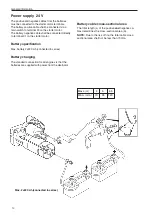
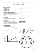
Page 12: ...nal 31 on the starter motor Battery specification Max battery 2x220 Ah connected in series Battery charging The standard connection for all engines is that the batteries are supplied with power from the alternator Max 2x220 Ah connected in series Max L m 4 5 6 5 Min A mm2 70 95 120 Battery cable cross sectional area The total length L of the positive and negative ca bles determines the cross secti...

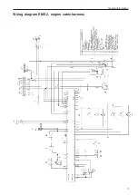
Page 13: ...General information 11 Wiring diagram EMS 2 engine cable harness ...

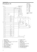
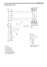
Page 14: ... diagram CIU Cable colors BL Blue LBL Light blue BN Brown LBN Light brown GN Green GR Gray OR Orange P Pink R Red SB Black VO Violet W White Y Yellow Wire cross section 0 75 mm2 unless otherwise stated 1 Ignition lock 15 2 RPM potentiometer 3 Tachometer code 14 4 Oil pressure instrument 5 Oil temperature instrument Does not apply for TAD734GE 6 Coolant temperature instrument 7 Instrument lighting ...

Page 15: ...iolet W White Y Yellow Cable cross section 0 75 mm2 unless otherwise stated 1 Stop switch 2 Start switch 3 1 pin connector block 4 Horn buzzer alarm 5 Easy Link connector block 6 RPM potentiometer 7 Indicator engine operation 8 8 pin connector engine interface 9 8 pin connector engine interface 10 Termination resistance 120 Ohm 11 Display Control Unit DCU ...

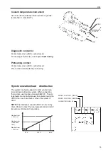
Page 16: ... mechanical wear sharp edges and water splashes If necessary run the cable through protective conduits Avoid making joints in the system as far as possible Cables and any joints must be accessible for inspec tion and service NOTE The connectors must be installed dry they must not be packed with Vaseline etc Connecting cable Connecting see section Instruments Extension cables are available in the f...

Page 17: ...spring biased Via parameter setting it can become energized during operation In that case use contact type closed NC RPM potentiometer Nominal rpm minus 120 rpm 0 3 1 9 V preset value 1 17 V Nominal rpm plus 120 rpm 1 9 4 7 V preset value 4 5 V 1500 1800 rpm contact This function allows a change of frequency from 50 to 60 Hz Contact type two position Idle contact Contact type two position Closed c...

Page 18: ...e Specs for all lamps Max load 3 W Voltage 24 V See Electrical diagram CIU Alarm low oil pressure Alarm high oil temperature Alarm high coolant temperature Alarm low coolant level Alarm fuel level Alarm battery voltage Overspeed indication Operation indicator Diagnostic lamp Preheating indication ...

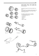
Page 19: ...y find their respective pa rameter group in the data bus Max length of Easy Link wiring is 3 m 10 ft The following instruments are available Tachometer operating hours Coolant temp Oil pressure Oil temp Battery voltage CIU cable harness 3 pin con nectors 3 pin con nector Extension cable 3 pin 1 0 m 3 ft 3 0 m 10 ft Attaching nut Attaching clamp ...

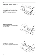
Page 20: ...104 302 F LBL R SB SB R BL OILPRESSURE INSTRUMENT Oil pressure instrument Use Volvo Penta oil pressure instrument graduated 0 10 bar 0 145 psi R BL TACHO METER GR SB R SB SB Instruments analogue optional See wiring diagram Tachometer Use Volvo Penta universal tachometer graduated 0 2600 rpm Set code 14 See Installation instructions ...

Page 21: ...on and load distribution system When connecting this system use interface module EAM122 The vol tage levels must simultaneously be adjusted using the VODIA tool as shown below when this system is used NOTE The interface module EAM122 is not sold by Volvo Penta Contact the local representative for GAC Governors of America Corporation LBN R SB SB R BL COOLANTTEMP INSTRUMENT Coolant temperature instr...

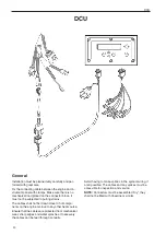
Page 22: ...s The cables shall not be drawn close to hot compo nents on the engine or close to any other heat source Ensure that the cables are protected from mechanical wear sharp edges and water splashes If necessary the cables can be feed through conduits Avoid having to make splices in the system wiring if at all possible The cables and any splices must be accessible for inspection and service NOTE Connec...

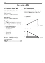
Page 23: ...eter group from the databus Maximum length of Easy Link cables is 3 m The following meters are available Tachometer operating hours Coolant temperature Oil pressure Oil temperature Battery voltage Charge pressure Alarm panel Warning and tell tale lamps Engine running indicator Max power 3 W Voltage 24 V DCU RPM potentiometer Max potentiometer value 0 10 V preset value 9 V Min potentiometer value 0...

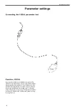
Page 24: ...n read off and adjust the parameters stated below The VODIA tool is con nected to the diagnostics connector 6 pin connector block located beneath the cable cover on the left side of the engine or by using T diagnostic connector no 874427 Refer to the VODIA user guide for help in using the tool Parameter settings Parameter settings ...

Page 25: ...n the ig nition is turned on If the parameter Off has been se lected pre heating must be activated manually via the ignition lock or pre heater button Alternative position Off or On Preset position Off Connected to system voltage during running stop EMS Stops input data to the CIU unit connected to system voltage at run or stop Preset position Stop Connected to system voltage during running stop C...

Page 26: ... coolant temperature Determines if engine protection shall be activated in response to high coolant temperature A fault code is registered and the engine is shut down Alternative position Off or On Preset value On Engine protector coolant level Determines if engine protection shall be activated in response to low coolant level A fault code is registered and the engine is shut down Alternative posi...

Page 27: ...ction to en gine speed differences Reduce the P value to reduce oscillations arising from large differences in speed load application An increased value Fig 2 gives a shorter response time Increase the P section for faster compensation to large differences in engine speed engine loading Fig 1 P section too low I value stabilizes Stability reacts to the time of the speed deviation A reduced value F...

Page 28: ...ges An increased value Fig 5 gives a reduced sensitivity to fast load changes Increase the D value to provide a better ability to compensate for fast changes Adjustment of PID regulator 1 Start the engine 2 Select the Engine with mounting and equipment and then Reinforcement and Stability calibration function groups in the VODIA tool 3 When calibration is started certain conditions must be met suc...

Page 29: ...s where the engine needs to be adjusted in crease or reduce the values of the P and I sections until unstable oscillating engine speed is obtained Then increase decrease the parameters until the en gine speed is stable again 6 If the engine is still unstable increase reduce the D section until engine speed only increases slightly when load is applied or removed please refer to figure 6 NOTE The fe...

Page 30: ...response as fig 6 9 Repeat the procedure in the other position High Low if necessary 10 To reset to factory settings use the reset button above the PID settings 11 Click Continue to finish calibration and follow the instructions to save the current settings in the con trol unit ...

Page 31: ...n 2 Change the frequency selector open or closed 3 Send a stop request by pressing on the stop but ton The whole procedure steps 1 to 3 may not take long er than 10 seconds With DCU Turn on the ignition and change the parameter in the DCU With SAE J1939 CAN Customers who use their own CAN bus based control unit must send certain messages to the engine TAD734GE in the same way as for the Volvo Pent...

Page 32: ...nt temperature too high 17 18 19 20 Coolant temperature too low 20 No or low charge 2 23 1 Flat batteries 2 Poor contact open circuit in ca bles 3 Main switch turned off 4 Main automatic breaker defec tive 5 Defective ignition switch 6 Defective main relay 7 Defective starter motor sole noid valve 8 Fuel shortage fuel taps closed fuel tank empty faulty tank connection 9 Blocked secondary fuel filt...

Page 33: ...t in the EMS 2 system this is indicated via the fault code fault reason on the instrument Both active unrectified and passive rectified faults are registered in the control system Refer to heading Running to read off fault codes fault messages The fault code list contains all the fault codes and fault messages together with information about caus es reactions and remedies that should be taken Re f...

Page 34: ...text is shown on the display ENGINE WARNING alternating with Press SEL for information NOTE You can select the language for the informa tion shown on the display Read the fault code as follows 1 Press the SEL button to come to the fault list The fault list shows Operation hours Fault cause Active inactive 2 Look up the fault code in chapter Fault codes and take the recommended actions 3 Press the ...

Page 35: ...lt which is displayed as flashes 3 Repeat steps 1 2 A new fault code will be flashed out if there are any more registered Repeat until the first fault code is repeated NOTE When the first fault code is shown again all fault codes have been shown If you press the diagnostics button after a fault has been rectified and the fault codes erased code 1 1 will be shown No faults Reading off a fault code ...

Page 36: ...2 2 PID SPN 111 Coolant level Reason Low coolant level Reaction Engine control module reduces engine power un less the protection has been shut off with the VODIA diagnostic tool Engine stopped Action Check the coolant level Check coolant level monitor function Code 2 3 PID SPN 111 Coolant level sensor Reason Short circuit to positive Fault in sensor Reaction None Action Check that the coolant lev...

Page 37: ...tion Check that the potentiometer is correctly con nected Check that the potentiometer cable is not dam aged Check potentiometer function Code 2 9 PID SPN 97 Indicator for water in fuel Reason Short circuit Open circuit Fault in indicator Reaction None Action Check the indicator cables for breaks and short circuits Check indicator function Change indicator as nec essary Code 3 1 PID SPN 100 Oil pr...

Page 38: ...ge air pressure sen sor Code 3 5 PID SPN 106 102 Charge pressure Reason Charge pressure too high Reaction Engine control module reduces engine power un less the protection has been shut off with the VODIA diagnostic tool Action Check turbocharger compressor function Check the function of the charge air pressure sen sor Check fuel volume injector Code 3 6 PID SPN 94 Fuel pressure sensor Reason Shor...

Page 39: ...arted The engine starts as soon as the ignition is switched on Action Check that the starter switch connections are not damaged Check that the wiring to the starter key is not damaged Code 5 3 PPID 6 SPN 520195 Stop input CIU Reason Short circuit to negative Open circuit Activated for too long time Reaction Engine can only be stopped with the auxiliary stop AUX STOP on engine Engine stops A fault ...

Page 40: ...maged Check that the cables between the CIU and the engine management unit are not damaged Code 6 5 SID 231 SPN 639 2017 PSID 201 Data link CAN EMS 2 Reason Internal fault in control module Reaction Engine not operating engine cannot be started Engine running engine idles and can only be stopped with the emergency stop AUX stop Action Check that the 8 pin connector is not damaged Check that the ca...

Page 41: ... aged Check fuel supply pressure Check the valve clearance Perform a compression test and check cylinder 2 Code 7 3 SID 3 SPN 653 Injector cylinder 3 Reason Electrical fault Faulty compression or injector Reaction Engine runs on 5 cylinders Abnormal sound Reduced performance Action Check that the unit injector cables are not dam aged Check that the injector connections are not dam aged Check fuel ...

Page 42: ...onnections are not dam aged Check fuel supply pressure Check the valve clearance Perform a compression test and check cylinder 6 Code 8 3 SID 42 SPN 679 Injection pressure regulator Reason Faulty cables Faulty actuator Fault in MPROP Reaction Engine control unit reduces engine power Action Please contact an authorized Volvo Penta work shop Code 8 3 PSID 96 SPN 1239 Pressure in Common Rail Reason L...

Page 43: ...ction It is not possible to activate pre heating Action Check cables Check the pre heating relay Code 9 3 SID 232 221 SPN 620 1079 1080 Voltage supply to sensor Reason Short circuit Fault in one of the sensors Reaction Faulty values in oil pressure and charge air pres sure sensors Fault code for oil pressure and charge air pressure sensors Low power Oil pressure and oil temperature instruments sho...

Page 44: ...Memory fault in engine management system EMS Reaction Engine might not start Action Re program the unit Code 9 9 SID 254 SPN 629 Control unit EMS Reason Internal fault in control module Reaction Engine misfires Engine does not start Action Change engine control unit ...

Page 45: ...43 References to Service bulletins Group No Date Concerning ...

Page 46: ... Notes ...

Page 47: ...ge write your comments on it and send it to us The address is at the bottom We would appreciate it if you were to write in English or Swedish From Refers to publication Publication no Date of issue Suggestion Motivation Date Name AB Volvo Penta Teknisk Information Avd 42200 SE 405 08 Göteborg Sweden ...

Page 48: ...7747352 English 10 2009 ...

Reviews: