General information
8
Fuel regulation
The engine’s fuel requirement is analyzed up to 100
times per second (depending on engine rpm). The en-
gine’s injection volume and injection timing are controlled
electronically via the fuel valves inthe injectors.
This means that the engine always has the correct
fuel volume under all running conditions, which gives
lower fuel consumption, the smallest possible exhaust
emission, etc.
The control unit controls and regulates the injectors
connected to a common rail, to ensure that the correct
fuel volume is injected into each cylinder. It also cal-
culates and adjusts the injection timing. Regulation is
performed mainly by using the engine speed sensor
and combination sensor for charge air pressure/charge
air temperature.
The control unit effects the unit injectors via an elec-
tronic signal to the solenoid fuel valve in each unit in-
jector, which can be opened and closed.
When the fuel valve is open, the fuel flows past,
through the hole in the unit injector and out via the fuel
channel. In this state, no fuel is injected into the cylin-
ders.
When the fuel valve is closed, pressure is built up by
the mechanically driven piston in the unit injector.
When sufficient pressure has been built up, the fuel is
injected into the cylinder via the unit injector’s injector.
The fuel valve opens again and the pressure in the
unit injector drops at the same time as injection into
the cylinder stops.
In order to decide when the fuel valve shall open and
close, the control unit has access to signals from sen-
sors and monitors.
Calculation of fuel volume
The control unit calculates the volume of fuel to be in-
jected into the cylinder. The calculation determines
the time during which the fuel valve is closed (when
the fuel valve is closed, fuel is injected into the cylin-
der). The parameters that determine the volume of
fuel injected are:
• Requested engine speed
• Engine protection functions
• The temperature
• Charge air pressure
High altitude adjustment
The control unit contains an air pressure sensor and
high altitude compensation for engines operating at
high altitudes.
The function limits the fuel volume in relation to the
ambient air pressure (the engine output is reduced
from approx. 1500 meters altitude). This is done to
prevent smoking, high exhaust temperatures and to
protect the turbocharger for overspeeding.
Diagnostic function
The purpose of the diagnostic function is to detect
and localize any faults in the EMS 2 system, to pro-
tect the engine and inform about any problems that
may occur.
If a fault is detected, this is shown with a warning lamp,
a flashing diagnostic lamp or a text message on the in-
strument panel, depending on the type of equipment fit-
ted. If a fault code is displayed as a flash code or as
text, this information is used as a guide when fault trac-
ing. Fault codes can also be read off by Volvos VODIA
tool at authorized Volvo Penta workshops.
If a serious fault occurs, the engine may be shut down
completely or the control unit may reduce the power
output (depending on the application). A fault code is
also displayed for guidance when fault tracing.
Connector for remote stop /
connector for “AUX-STOP”
●
Maximum cable length 8 meters (4 meters from
connector and back).
●
Minimum cable cross-section 2.5 mm
2
●
Never
use the “AUX-STOP” as the normal stop
button.
●
It is not permitted to use the “AUX-STOP” at the
same time as the normal stop button*.
●
If an emergency stop is fitted, we cannot guaran-
tee that the EMC requirements are fulfilled, since
this can effect how the the cabling is connected.
*
NOTE!
If the ”AUX-STOP is used at the same time as the nor-
mal stop button, the Common Rail system may be seriously
damaged.
Summary of Contents for TAD734GE
Page 1: ...EMS 2 Industrial engines TAD734GE Installation 1 1 I ...
Page 2: ......
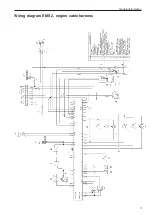
Page 13: ...General information 11 Wiring diagram EMS 2 engine cable harness ...
Page 45: ...43 References to Service bulletins Group No Date Concerning ...
Page 46: ... Notes ...
Page 48: ...7747352 English 10 2009 ...


