background image


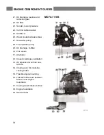
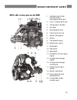
MD7A with reverse gear model MSB 


1.  Oil dipstick and oil filler 

hole hole and oil 
scavenging reverse gear 

2.  Cover, cooling water pump 

3.  Venting screw, fine-filter 

4.  Fine-filter 

5.  Decompression lever 

6.  Fuel pressure line nut 

7.  Sender, temp gauge 

8.  Injector 

9.  Thermostat housing 

10.  Oil filler hole, engine 

11.  Hand starter 

12.  Stop device 

13.  Speed lever 

14.  Oil dipstick, oil scavenging 

engine 

15.  Cooling water drainage, 

engine 

16.  Cooling water drainage, 

reverse gear 

17.  Air filter and air intake 

silencer 

18.  Sender, tachometer 

19.  Fuel pump (with hand 

priming device) 

20.  Cooling water intake, 

reduction gear 


33 


ENGINE COMPONENT GUIDES 

Summary of Contents for MD7A

Page 1: ......

Page 2: ......

Page 3: ...ould be studied carefully Also included is a report card which is to be completed by the dealer or boat seller and forwarded to Volvo Penta However if our warranty is to apply it is an absolute condition that the measures given in the Check and Service Scheme are carried out and that your engine and equipment are looked after according to the instructions in this book When in doubt always get in t...

Page 4: ......

Page 5: ...Service Scheme 12 Checks and Service 13 23 Check daily before starting Check every 14 days Service every 50 hours of operation Service every 100 hours of operation Venting the fuel system Service when laying up and launching 13 13 14 15 16 17 22 23 24 28 Fault Tracing Scheme 29 Technical Data 30 31 Wiring Diagram 32 Engine Component Guide 33 34 Index alphabetical order 35 CONTENTS ...

Page 6: ...ide mounting 1 Control lever 2 Disengaging button Push in the button when the control lever is in neutral and move the lever a bit forwards Release button The lever is now used only for engine speed control To use the lev er for both engine speed control and gear changing push in the button and pull back the lever to neutral position and move it again Forward or Reverse N Neutral F Control lever i...

Page 7: ...engine has been run for 20 hours See further under Checks and Service ENGINE SPEED Max engine speed MD7A 43 4 rev sec 2600 rpm In order to select the correct propeller reference is made to the Volvo Penta propeller diagram Check the engine speed with normal load in the boat I n order to obtain maximum engine performance an engine speed as high as possible should be chosen but not however greater t...

Page 8: ...ing to e g weather reports COMPASS which is deviated BOAT HOOK and paddle MOORING ROPES FOG HORN and whistle FLOATING ANCHOR TORCH PREPARATIONS BEFORE STARTING Make sure that There is no FUEL LEAKAGE There is no WATER LEAKAGE from engine and hull There is no OIL LEAKAGE There is no SMELL OF LP GAS in the deep cavities in the boat or elsewhere The OIL LEVEL is correct There is enough FUEL for the p...

Page 9: ... up Return the de compression handle for running when the engine has been cranked up in speed Cold weather starting CAV fuel injection pump Starting is facilitated if the cold start control is pulled out The cold start control must be pushed in after the engine has started BOSCH fuel injection pump The engine has a built in automatic cold start device Check immediately after starting that the warn...

Page 10: ...eed for long periods of time Check regularly during running that the warning lamp for battery charging is out Should the cooling water temperature be too high or the oil pressure too low the buzzer will warn you at the same time the relevant warning lamp goes on If this happens the engine must be stopped immediately and the reason investigated SHUTDOWN PROCEDURE Before shutdown the engine should b...

Page 11: ... off the main switch NOTE The main switch must never be switched off until the engine has stopped completely the charging regulator can be damaged Close the fuel and cooling water cocks if the boat is not going to be used for some time Check for leakage before leaving the beat In cold weather and whenever there is a risk of temperatures below zero the cooling water must be drained from the engine ...

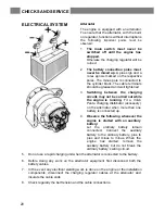
Page 12: ... pressure from becoming excessive ELECTRICAL SYSTEM The engine has a starter motor and an alternator with built in rectifier Voltage regulation is performed by a transistorized regulator mounted on the alternator The alternator makes it possible to charge two batteries independent of each other if a double diode accessory is fitted to the alternator A main fuse which can easily be re connected is ...

Page 13: ... the BOSCH fuel injection pump the cold start device is operated automatically COOLING SYSTEM The engine is cooled by sea water The cooling system has a sea water pump and a water distributor housing with a thermostat The sea water pump has an impeller made of neoprene rubber which is driven via a rubber flange from the camshaft The thermostat in the water distribution housing regulates the water ...

Page 14: ... gear The power from the engine to the reverse gear is transmitted via a rubber flange For operating Forward and Reverse the Volvo patented cone clutch is used which ensures smooth and quiet engagement Very small forces are required to operate the reverse gear TECHNICAL DESCRIPTION ...

Page 15: ...ne is transmitted via a rubber flange carrier to the S Drive For operating Forward and Reverse the Volvo patented cone clutch is used which ensures smooth and quiet engagement Very small forces are required to operate the reverse gear TECHNICAL DESCRIPTION ...

Page 16: ...4 14 SERVICE EVERY 50 HOURS OF OPERATION Change the engine lubrication oil Change the reverse gear lubrication oil every 200 hours Change the lubrication oil in the S Drive model 110S Valve clearance Checking and adjusting 15 15 16 16 SERVICE EVERY 100 HOURS OF OPERATIONS OR AT LEAST ONCE EACH SEASON Change the oil filter Clean the air filter Checking and changing the alternator v belt Check tight...

Page 17: ... of oil see under Technical Data CHECKS every 14 days OIL LEVEL IN REVERSE GEAR Unscrew the dipstick wipe it clean and insert it again without screwing it down Pull up the dipstick and check the oil level which should be between the marks If necessary top up with oil Do not top up above the MAX mark Screw down the dipstick again Note that there is a sealing washer on the dipstick Concerning choice...

Page 18: ...ck Concerning choice of oil see under Technical Data Page 30 THE ELECTROLYTE LEVEL IN BATTERY The level should be between 5 10mm 3 16 3 8 above the cell plates in the battery If necessary top up with distilled water NOTE Exercise great care when doing this The electrolyte is corrosive and the gas being formed is explosive THE BELT TENSION Correct belt tension is necessary for full alternator outpu...

Page 19: ...a NOTE Change also the oil filter at every second change of oil See page 17 OIL CHANGE IN REVERSE GEAR every 200 hours of operation or at least once per season The oil can be drained from the reverse gear by removing the plugs under the reverse and reduction gears respectively see Engine Component Guide or by sucking up the oil through the dipstick hole with the help of an oil scavenging pump Fill...

Page 20: ...he plug with its O ring Fill oil through the dipstick hole The oil level shall be within the dipstick marks NOTE Do not fill oil above the upper oil dipstick mark Concerning the choice of oil see Technical Data Page 30 VALVE CLEARANCE Checking and adjusting the valve clearance should be done by an authorized Volvo penta Service Workshop See further under Valves Technical Data CHECKS AND SERVICE ...

Page 21: ...urface Turn the filter a further half turn not more NOTE Only use a genuine Volvo oil filter Start the engine run at idling and check that the oil pressure warning lamp goes out Check oil level and that there are no leaks from the contact surface of the oil filter CLEANING OF AIR FILTER The air filter should be removed and cleaned after every 100 hours of operation or once per season Loosen the cl...

Page 22: ...gain after 20 hours of operation The valve clearance should always be checked after the nuts have been retightened Sequence for tightening nuts is shown in the figure opposite ZINC ANODE PROPELLER S DRIVE 110S Replace the zinc anode if it is eaten away to more than 50 Remove the propeller and the spacer ring with deflector and remove the Allen head screws holding the zinc anode Clean the contact s...

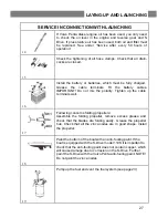
Page 23: ...ng rings can be damaged when the shaft is pushed back Remove the locking screw on earlier executions hold back the shaft pull off the impeller Install a new impeller tighten the screw and push the shaft back into position The carrier is defective if the impeller and shaft can be turned A new carrier can be installed after having removed the pump Install the water pump cover using a new gasket Open...

Page 24: ...lvo Penta charging distributor accessory on the alternator when more than one battery is connected up 4 Observe the following whenever the engine is started with an auxiliary battery Let the ordinary battery remain connected Connect the auxiliary battery to the ordinary battery plus to plus and minus to minus When the engine has started remove the auxiliary battery but do not break the ordinary ba...

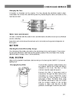
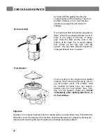
Page 25: ...ich shows the specific gravity of the electrolyte this varying with the state of charge See Technical Data FUEL SYSTEM Observe the greatest cleanliness when working on the fuel system NOTE Try to avoid spilling fuel Changing the fuel filter The fuel filter must be replaced least once per season NOTE If an extra fuel filter is installed in the boat this filter or filter element must be replaced as ...

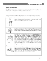
Page 26: ... The fuel filter element should be changed at least once a season Fuel Strainer The fuel pump on the engine has a built in strainer which can be removed by remov ing the pump s cover The strainer must be cleaned at least once per season Always vent the fuel system See Ven ting of Fuel System page 23 Check immediately after starting that there is no fuel leakage Injectors All work on the engine inj...

Page 27: ... removed or when first starting a new engine the injection pump must be vented BOSCH Fuel Injection pump Operate the handprimer for approximately half a minute The injection pump is then automatically vented CAV Fuel Injection pump has two air venting screws see picture Vent No 1 and then No 2 Operate handprimer until fuel free from air bubbles flows out at screw No 1 Tighten screw No 1 Put thrott...

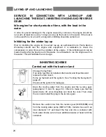
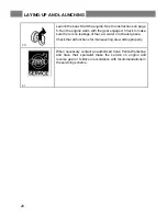
Page 28: ...the boat is out of the water it is advisable to run the engine warm in the water This will facilitate the oil change INHIBITING SCHEME Carried out with the boat on land 1 Change the fuel filter If an extra fuel filter is installed drain water and impurities and replace the filter insert Pump up fuel and vent the system See Venting the fuel system page 23 Check out the system for leakages 2 Drain t...

Page 29: ... be of the type Esso Rustban 623 Shell Ensis Oil or of an equivalent type If inhibiting oil is used the oil filter must be replaced at the time of launching the boat 7 Prepare a rust protection mixture consisting of fresh water and 5 Volvo Penta rust protection oil and emulsifying oil NOTE Water first and then the oil Following rust protection oils can also be used Esso Cutwell 40 Shell Donax C or...

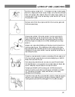
Page 30: ...nt Spray the components of the electrical system and all control components with anti moisture spray 11 Remove the battery For proper maintenance it needs to be charged to prevent it from being damaged 12 Check the flexible rubber seal between the S Drive and the engine foundation for elasticity and that it is free from mecha nical damage The flexible rubber seal must replaced each 5th year Check ...

Page 31: ...x the polarity Tighten up the cable terminals well 17 Following concerns folding propellers Assemble the folding propeller remove excess grease and check that the blades are folding easily Grease the propeller hub Check that all the zinc anodes are in good shape Install the propeller 18 Paint the bottom of the boat with an anti fouling paint If the boat is equipped with the S Drive model 110S itis...

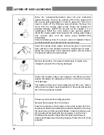
Page 32: ...e is no leakage of fuel air water or exhaust gases Check that all functions for maneuvering are working properly 21 When necessary contact an authorized Volvo Penta Workshop and have their specialist make the service on engine and reverse gear or S Drive in accordance with recommendations in the servicing scheme LAYING UP AND LAUNCHING ...

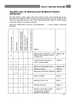
Page 33: ... start Engine stops Engine does not reach correct operation speed at full throttle Engine runs unevenly or vibrates abnormally Engine becomes abnormally hot Reason See X Main switch not switched on flat battery break in electric circuit or blown fuse Pages 5 20 21 X X Empty fuel tank closed fuel cock blocked fuel filter Page 22 X X X Water air or impurities in fuel Pages 21 23 X X X X Defective in...

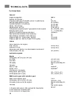
Page 34: ...e mm in Lubrication system Engine Oil capacity din 3 imp qts US qts incl filter excl filter Oil quality Viscosity above 100 C below 10 0 C Oil pressure hot engine idling speed kp cm2 psi at full speed kp cm 3 psi MSB reverse gear with reduction gear Ratio with reduction gear Oil capacity din 3 imp qts US qts Oil quality same as for the engine Viscosity 1 Propeller shaft output to DIN Leusting B f ...

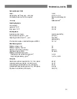
Page 35: ...y max Ah Starter motor rating kW Hp Alternator rating A W Battery electrolyte spec grav Charging to be carried out at g cm t3 Fully charged battery g cm t3 Torques Stud bolts cylinder head M10x 1 5 Nm kpm Cylinder head nuts M10x 1 0 Nm kpm Connecting rod bolts M10x 1 5 Nm kpm Crankshaft main bearing M10x 1 5 Nm kpm Flywheel nut M16x2 Nm kpm 1 66 1 2 3 2 0 2 4 Diesel Lubricating Oil CD SAE2OW 302 6...

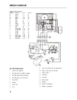
Page 36: ... 0 75 18 K Blue Yellow 0 75 18 L White Red 0 75 18 M Blue Red 0 75 18 List of Components 1 Switch extra lighting 2 Warning lamp no battery charging 3 Warning lamp high temperature 4 Warning lamp low oil pressure 5 Key switch 6 Buzzer 7 Alarm unit 8 N A 9 Place for instruments opt equipment 10 Plug in connector wire harness 11 Starter motor 12 Alternator 13 Fuse box 14 Main switch 15 Battery 16 Sen...

Page 37: ...ure line nut 7 Sender temp gauge 8 Injector 9 Thermostat housing 10 Oil filler hole engine 11 Hand starter 12 Stop device 13 Speed lever 14 Oil dipstick oil scavenging engine 15 Cooling water drainage engine 16 Cooling water drainage reverse gear 17 Air filter and air intake silencer 18 Sender tachometer 19 Fuel pump with hand priming device 20 Cooling water intake reduction gear 33 ENGINE COMPONE...

Page 38: ...injection pump 29 Oil drainage S Drive 30 Zinc anode 31 Alternator 32 Closed crankcase ventilation 33 Oil dipstick and oil filler hole S Drive 34 Closing cock for incoming cooling water 35 Flexible engine mounting 36 Flexible rubber seal between S Drive and engine foundation 37 Cooling water intake S Drive 38 Engine foundation 39 Starter motor MD7A 110S 34 ENGINE COMPONENT GUIDES ...
Page 39: ...ations before starting 4 Electrical system 8 20 32 Reverse gear 10 Engine body 8 Running 6 Engine component guides 33 34 Safety equipment 4 Engine speed 3 S Drive Model 110S 11 Sea water pump 19 Fault tracing scheme 29 Spare battery 20 Fine filter 21 22 34 Starter motor 21 Fuel 3 Starting 5 Fuel filters 21 22 Fuel pump 22 Technical data 30 31 Fuse box 21 Thermostat housing 33 34 Hand priming pump ...

Page 40: ......

Page 41: ...sh water tank and the toilet can be damaged by frost To Be Checked The steering gear and controls must function perfectly and their operation should be checked at regular intervals Never take any chances if you suspect that something is wrong Take immediate action to remedy faults All rubber ages so check all rubber parts at regular intervals Parts which are of special importance are the fuel hose...

Reviews: