background image

35

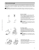
Fuel pre-filter. Draining and replacing
filter insert

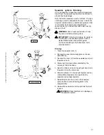
Draining
The fuel pre-filter is an optional extra.

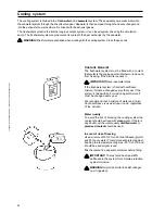
Position a container under the fuel filter. Drain off
water and contaminants using the cock/plug at the
bottom of the glass.

IMPORTANT! Wait a few hours after the engine
has been turned off before draining the filter.

Replacing filter insert
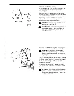
Close fuel cock at the fuel tank. Position a container
under the fuel filter.

Remove the glass bowl by slackening off screw (1).
Empty and clean glass. Replace insert and reinstall
glass. Open fuel cock. Vent fuel system. Deposit the
old filter insert at a properly designated disposal
site.

Start the engine and check for leaks.

WARNING! Approaching or working on a running
engine is dangerous. Watch out for rotating
components and hot surfaces.

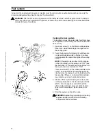
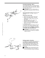
Fuel filter. Changing

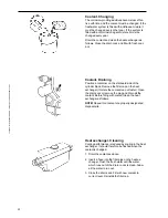
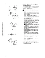
Clean the filter mounting. To avoid fuel spills put a
plastic bag over the filter before it is unscrewed.
Unscrew the filter. Moisten the filter rubber gasket
with a little oil. Screw on the new filter by hand until it
is in contact with the mating surface. And then a
further half turn but no more! Vent fuel system.
Deposit the old filter at a properly designated
disposal site.

Start the engine and check for leaks.

 WARNING! Approaching or working on a running

engine is dangerous. Watch out for rotating
components and hot surfaces.

1

7741986 - Downloaded from www.volvopenta.com 06/10/2006 13:10:27

Summary of Contents for MD2010

Page 1: ...OPERATOR SMANUAL MD2010 MD2020 MD2030 MD2040 ...

Page 2: ...s på svenska Beställningskupong finns i slutet av instrukti onsboken Questo manuale d istruzioni può esse re ordinato in lingua italiana Il tagliando per l ordinazione è riportato alla fine del manuale Dit instructieboek kan worden besteld in het Nederlands De bestelcoupon vindt u achter in het instruc tieboek Denne instruktionsbog kan bestilles på dansk Bestillingskupon findes i slutningen af in ...

Page 3: ...onment where traditional Volvo Penta qualities such as first class performance reliability and durability have been upheld We believe that this also reflects what you require and expect from your new marine engine To help you fulfill your expectations we want you to read through this operator s manual carefully and take our advice about operating and maintaining the engine before you cast off on y...

Page 4: ...precautions 22 Maintenanceschedule 23 24 Maintenanceandcare 25 51 Engine general 25 Lubrication system 27 Cooling system 28 Fuel system 34 Electrical system 36 Wiringdiagram 41 S drive and reverse gear 45 Layingup Launching 49 51 Inhibiting 49 Bringing out of storage 50 Painting the drive and underwater hull 51 Fault tracing 52 TechnicalData 53 54 General 53 Lubrication cooling and electrical syst...

Page 5: ...is symbol is used in the book and on the engine to make you aware of safety information Always read these safety precautions very carefully In the operatror s manual warning texts have the following priority WARNING If these instructions are not followed there is a danger of personal injury exten sive damage to the product or serious mechanical malfunction IMPORTANT Used to draw your attention to ...

Page 6: ...artment visually before operating the boat before the engine is started and after operating the boat after the engine has been stopped This will help you to quickly detect fuel coolant and oil leaks and spot anything else unusual that has or is about to happen Maneuvering Avoid violent and unexpected changes in course and gear engagement This could cause someone on the boat to lose their balance a...

Page 7: ...ealer where the boat was purchased to get more information on how to solve this problem should it occur on your boat Checklist Safety equipment Life jackets for all passengers communication equipment emergency rockets approved fire extinguisher first aid equipment life belt anchor paddle torch etc Replacement parts and tools impeller fuel filters fuses tape hose clamps engine oil propeller and too...

Page 8: ...d in order to maintain the correct balance and make the engine safe to handle Never carry out work on an engine suspended on a hoist Beforestartingtheengine Reinstall all guards removed during service operations before starting the engine Check that no tools or other items have been left on the engine Never start a turbocharger engine without installing the air cleaner ACL The rotating compressor ...

Page 9: ...must be carried out with the engine at operat ing temperature and the coolant filler cap or a cock open or a coolant hose disconnected open the coolant filler cap carefully and slowly to release pressure before removing the cap completely Note that the coolant may still be hot and can cause burns Lubrication system Hot oil can cause burns Avoid skin contact with hot oil Ensure that the lubrication...

Page 10: ... as waste oil coolant paint and wash residue flat batteries etc for disposal at a destruction plant Our joint efforts will make a valuable contribution to our environment Running in The engine must be run in for its first 10 operating hours as follows Operate the engine normally Do not operate it at full load except for short periods Never run the engine at a constant engine speed for long periods...

Page 11: ...s contained in the operator smanualconcerningoperation serviceand maintenance must be followed IMPORTANT Lateorinadequatemaintenance service or the use of spare parts other than Volvo Penta original spare parts will invalidate AB Volvo Penta s responsibility for the engine specification being in accordance with the certificated variant Volvo Penta accepts no responsibility or liability for any dam...

Page 12: ...0 with reverse gear MS10L MD2020 with sailing boat drive MS25S MD2020 with sailing boat drive MS25S 9 11 12 13 14 15 8 10 7 21 20 9 10 12 13 14 15 8 11 17 18 1 3 6 5 4 19 2 4 1 7 2 3 6 4 5 4 7741986 Downloaded from www volvopenta com 06 10 2006 13 10 27 ...

Page 13: ...2030 with reverse gear MS10A 9 Oil filler cap engine 10 Dipstick engine 11 Air cleaner ACL Air intake 12 Seawaterpump 13 Injection pump 14 Lubricating oil filter 15 Fuelpump 16 Oil cooler reverse gear 17 Foldingpropeller 18 Cooling water intake S drive 19 Sea cock S drive 20 Oil drain plug S drive 21 Sacrificialanode 11 10 13 14 15 8 9 1 2 3 6 4 5 4 16 12 11 9 12 13 14 15 8 10 7 1 7 2 3 6 4 5 4 77...

Page 14: ...y should the boat be stolen The appearance and location of identification plates is shown below The figures in brackets refer to the location of the identification numbers on the identification plate Engine Productdesignation 1 Serialnumber 2 Productnumber 3 Certificationnumber 4 S drive Reverse gear Productdesignation 5 Serialnumber 6 Productnumber 7 Gear ratio 8 Propellerdesignation Engineplate ...

Page 15: ...nd tenths of an hour 2 Siren for acoustic alarm 3 Warning display See 16 19 4 Switch for instrument lighting 5 Alarm test acknowledgment switch To test alarm Press the switch All warning lights light and the acoustic alarm sounds Alarm acknowledgment Press the switch if there is an alarm The acoustic alarm stops but the relevant warning lamp continues to flash until the malfunction is corrected 6 ...

Page 16: ...e speed Multiply this value by 100 for revolutions per minute The hour counter displays engine operating time in hours and tenths of an hour 11 Siren for acoustic alarm 12 Warning display See 16 19 13 Switch for connecting and disconnecting instru ment panel 14 Starter button The starter motor is engaged when this button is pressed 15 Alarm test acknowledgment and glow plug rocker switch Glow plug...

Page 17: ...te 18 Generatornotcharging 19 Indicator lamp Comes on when the glow plugs are activated Check that the warning lamps are operating before starting the engine according to the description of the relevantinstrumentpanel Extra warning display If the acoustic alarm sounds one of the four warning lamps starts to flash to indicate the source of the alarm The extra warning display is an accessory 20 Not ...

Page 18: ...ing the screw clockwise makes the lever movement stiffer while turning counterclockwise makes it easier to move the lever Reinstall the cover and lever Maneuvering Shifting and engine speed are controlled with the same lever 1 N Neutral position Drive reverse gear disengaged F Drive reverse gear engaged for movement ahead R Drive reverse gear engaged for movement astern T Engine speed control Dise...

Page 19: ... on the main switch IMPORTANT Never break the circuit with the main switch while the engine is running This could damage the generator Start the engine compartment fan if one is fitted and let it run for at least four minutes Check that there is sufficient fuel Push in the stop control Starting Instrument panel with ignition lock WARNING Never use start spray or similar to start the engine Danger ...

Page 20: ...e engine again 5 Warm up the engine at low speed and low load IMPORTANT Do not race the engine while it is cold Starting Instrument panel without ignition switch WARNING Never use start spray or similar to start the engine Danger of explosion 1 Move the control lever to the neutral idle position 2 Activate the instrument panel by pressing the Power ON OFF switch The three warning lamps come on and...

Page 21: ...atteries have the same rated voltage as the engine s system voltage 2 First connect the red jump lead to the discharged battery s termi nal A and then to the auxiliary battery s terminal B 3 First connect the black jump lead to the auxiliary battery s termi nal C and then to a site D where there is good contact with the cylinder block as far away from the discharged battery as possible 4 Start the...

Page 22: ...is too low IMPORTANT If the alarm sounds Stop the engine immediately Investigate and correct the malfunction Engine coolant temperature ECT B Normal operating temperature is between 75 90 C The acoustic alarm will automatically go off if the engine coolant temperature ECT is too high IMPORTANT If the alarm sounds Reduce engine speed to idle neutral Stop the engine if the temperature does not drop ...

Page 23: ...most of its speed 2 Move the reverse gear control lever quickly and firmly into the neutral position Wait for a moment 3 Move the gear control lever quickly and firmly into astern then increase the speed 1 2 3 When sailing If the boat has a fixed propeller the control lever must be in the neutral position when sailing If the boat has a folding propeller the control lever must be in the astern posi...

Page 24: ...rget to open the cocks before the engine is startedagain Switch off the main switch if the boat is not to be used for some time IMPORTANT Never break the circuit with the main switches while the engine is running This could damage the generator Laying up If the boat is not going to be used for some time but is being left in the water the engine must be run to operating temperature at least once ev...

Page 25: ...it as little as possi ble Preventive maintenance in accordance with the maintenance schedule will ensure that it retains these qualities and avoid unnecessary operational disturbances Warranty inspection The prescribed warranty inspection First Service Inspection must be carried out at an authorised Volvo Pen ta workshop during this first period of operation Directions for when and how this is to ...

Page 26: ... every other year Least once a year Foldingpropeller Cleaning page46 S drive Check rubber seal hull drive page48 Every 400 operating hours or at least once every two years Air Cleaner ACL Check page 25 Coolant 1 Replace page 30 Heat exchanger Cleaning page 30 Injectors Test pressure not shown Valve clearance Adjustment not shown 1 If the freshwater system is filled with an anti corrosion agent mix...

Page 27: ...in switch Engine general Air Cleaner ACL Cleaning Clean the filter when necessary by cleaning it with a soap solution Rinse afterwards in clean water Squeeze out the filter and allow to dry MD2020 MD2030 MD2040 Remove the hose clamp 1 and remove the filter Remove the spring inside the filter Clean the filter IMPORTANT Take care that no contaminants enter the engine Drive belt Check The belt drives...

Page 28: ...es Install the new belt Adjust as above Check belt tension again after a few hours operation Idling Adjustment For engine idling speed Please refer to the Technical Data chapter A lower engine speed can cause the engine to stall and a higher engine speeds can cause extra stresses to the drive reverse when shifting Adjust with the engine at operating temperature as follows 1 Set the control lever i...

Page 29: ...il and oil filters Changing 1 Run the engine to operating temperature so that the oil is easier to suck out Stop the engine 2 Suck out the oil using an oil drain pump through oil drain pipe 1 WARNING Hot oil and hot surfaces can cause burns 3 Unscrew the old filter To avoid oil spills put a plastic bag over the filter before it is unscrewed 4 Check that the engine mating surface is clean 5 Moisten...

Page 30: ...ure water This mixture will protect against freezing to a temperature of approx 40ºC 40ºF and should be used all year round Mix the coolant in a separate container before filling IMPORTANT There should be at least 40 antifreeze in the system for complete protection againstcorrosion WARNING Glycol is harmful to health danger ous if ingested Cooling system The cooling system is divided into a freshw...

Page 31: ...e foam and drastically reduce the cool ant s effectiveness Coolant level Checking and topping up WARNING Do not open the engine coolant system filler cap when the engine is still hot except in an emergency Steam or hot coolant may spray out Turn the filler cap to the first stop and let any pressure escape from the system before removing the cap Top up coolant if necessary The level should lie betw...

Page 32: ...en the coolant is changed 1 Drain the coolant as above 2 Insert a hose into the filler pipe on the heat ex changer Flush the fresh water until the water which runs out of the drain cocks is clean Allow all the water to run out 3 Close the drain cock Fill with new coolant to correct level Reinstall the filler cap Coolant Draining Position a container on the starboard side of the cylinder block Remo...

Page 33: ...etration Close the sea cock Close the sea cock Disassemble the valve Unscrew the hexagonal cover In the cover there is a mem brane and a gasket Clean all the parts Turn the cover upside down Install the membrane first and then the gasket Turn the valve housing upside down as well Screw the cover into position but not too hard 0 2 kpm or the valve may stop working Seawater filter Cleaning The seawa...

Page 34: ...ree end of the hose in a bucket of fresh water Fill the system IMPORTANT The impeller will be damaged if it runs dry 4 Check that there is nobody close to the propeller and there is nothing that will get splashed behind the exhaust outlet 5 Set the control lever to neutral Start the engine Let the engine run at fast idle for a few minutes Stop the engine 6 Fill the bucket with an anti freeze mixtu...

Page 35: ...osion according to the instructions in the previoussection Draining 1 Close the seawater cock 1 2 Remove the cover and sealing plate on the sea water filter 2 3 Remove the cover 3 from the seawater pump Let the water run out 4 Disconnect the hoses where indicated by the arrows 4 Drain the hoses 5 Open the drain cock 6 on the exhaust riser Drain the water Close the drain cock 6 Drain the silencer 7...

Page 36: ...el Continue pumping and at the same time tighten the venting screw NOTE If the pump output is low turn the engine so that the marking on the pulley is at TOP see the illustration If the pump output is still low turn the engine one more revolution to TOP There is a strainer 3 in the intake manifold for the pump The strainer does not normally need to be cleaned since the engine should be installed w...

Page 37: ...properly designated disposal site Start the engine and check for leaks WARNING Approachingorworkingonarunning engine is dangerous Watch out for rotating components and hot surfaces Fuel filter Changing Clean the filter mounting To avoid fuel spills put a plastic bag over the filter before it is unscrewed Unscrew the filter Moisten the filter rubber gasket with a little oil Screw on the new filter ...

Page 38: ...it with the main switches while the engine is running Electrical connections Also check that all electrical connections are dry and free of oxidation and that there are no loose connec tions If necessary spray these connections with a water repellent spray Volvo Penta Universal oil Fuses The engine has a fuse holder with four 15 A fuses This is located on the relay box to the left at the rear of t...

Page 39: ... connect the red battery lead to the battery terminal Then connect the black battery lead to the battery terminal When disconnecting the battery disconnect the lead black first and then the lead red Cleaning Keep batteries dry and clean Oxidation or dirt on the battery and battery terminals can cause short circuits voltage drop and discharge especially in damp weather Clean the battery terminals a...

Page 40: ...the boat has not been used for some time charge the battery and then trickle charge it see manufacturer s recommendations A poorly charged battery will be damaged and may burst in cold weather IMPORTANT Follow the instructions supplied with the battery charger carefully To avoid electrolytic corrosion when an external charger is connected always disconnect the battery leads before connecting the c...

Page 41: ...etc must be intended for marine usage and the high tension circuit must be galvani cally separated from the low tension circuit 2 Route and clamp electric cables so that they will not be exposed to rubbing damp or bilge water in the keelson 3 The drive reverse gear and flywheel cover are electrically isolated A from the engine and must never be used as a ground IMPORTANT Thedrive reversegearand fl...

Page 42: ...power consuming equip ment connected to that battery and be turned off when power is no longer needed All equipment connected to the auxiliary battery should have separate switches To simultaneously charge two independent battery circuits fit a Volvo Penta charge distributor ac cessory to the regular generator D 7741986 Downloaded from www volvopenta com 06 10 2006 13 10 27 ...

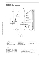
Page 43: ...ne 11 Oil pressure gauge 12 Coolant temperature switch 13 Engine coolant temperature sensor 14 Connector 16 pin Cable areas in mm2 are indicated after the color codes in the wiring diagrams Areas not indicated 1 0 mm2 A broken line indicates a non Volvo Penta cable Cable color BL Blue OR Orange LBL Light blue R Red BN Brown SB Black LBN Light brown W White GN Green Y Yellow GR Gray 7741986 Downloa...

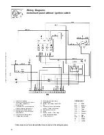
Page 44: ... 7 Charge warning lamp 8 Glow plug indicator lamp 9 Starter button 10 Button Instrument panel Off On 11 Connector for neutral position switch if fitted accessory 12 Semiconductor diode 13 Alarm 14 Rocker switch Glow plug Alarm test acknowledge 15 16 pin connector Cable color BL Blue BN Brown GN Green GR Gray OR Orange PU Purple R Red SB Black W White Y Yellow Cable areas in mm2 are indicated after...

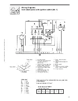
Page 45: ...Switch instrument panel lighting 10 Alarm test acknowledgment switch 11 Ignition switch 12 Alarm 13 Connector for neutral position switch if fitted accessory 14 16 pin connector Spring loaded Spring loaded Cable color BL Blue BN Brown GN Green GR Gray OR Orange R Red SB Black VO Violet W White Y Yellow Cable areas in mm2 are indicated after the color codes in the wiring diagrams Areas not indicate...

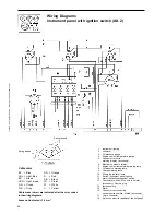
Page 46: ...5 Connector for extra warning display accessory 6 Electronics module alarm 7 Engine coolant temperature warning lamp 8 Oil pressure warning lamp 9 Charge warning lamp 10 Glow plug indicator lamp 11 Switch instrument panel lighting 12 Alarm test acknowledgment switch 13 Tachometer with built in hours run meter accessory Dummy plug 14 Ignition switch 15 Alarm 16 Connector for connecting neutral posi...

Page 47: ... the oil level The correct oil level is between the MAX and MIN markings Top up the oil as required using the dip stick tube For oil quality and capacity See the chapter Technical Data IMPORTANT Do not overfill under any circum stances The oil level must always be within the recommendedlevel Oil change Reverse gear Remove the oil dipstick Suck up oil using an oil pump through the hole for the dips...

Page 48: ...re is a good metal contact 5 Reinstall the propeller The sacrificial anodes oxidise when they come into contact with air This reduces the galvanic protec tion There may even be oxidisation on the surface of a completely new anode Always clean the sacri ficial anodes before launching the boat IMPORTANT Use emery paper Do not steel tools when cleaning as these may damage the galvanic protection Fold...

Page 49: ...hread sealant to the locking screws 9 After the locking screws have been tightened apply thread sealant to the screw heads as well 3 Drive Locate the tab washer 3 on the nut Install and tighten the locking screw 4 to 20 Nm and bend one of the tab washer tabs to the screw head IMPORTANT The tab washer 3 must be re placed if necessary Use only Volvo Penta ori ginal locking screws 4 4 Install one pro...

Page 50: ...n press in approx 1 cc water repellent grease into the seal IMPORTANT The seal must be replaced every 500 running hours or every 5th year Rubber seal S drive Check the rubber seal between the drive and the hull regularly for cracks and wear WARNING The seal must be changed every seven years or earlier if it is defective This work should be carried out by an authorized workshop 7741986 Downloaded f...

Page 51: ...and seawater filter ac cessory Clean and inhibit the seawater system Remove the impeller from the seawater pump Store the impeller in a sealed plastic bag in a cool place Check the condition of the engine coolant anti freeze Top up if required IMPORTANT An anti corrosion mixture in the engine coolant system provides no protection against freezing If there is any possibility the engine will be subj...

Page 52: ...el and antifreeze protec tion Top up if necessary Connect the fully charged batteries Paint the drive and hull See next page Check the sacrificial anode on the drive If there is less than 50 of the anode left it must be re placed Clean with emery cloth just before the boat is launched IMPORTANT Do not use a wire brush or other steel tools when cleaning as these may damage the galvanic protection R...

Page 53: ...kdamageisremedied Sand down metal surfaces lightly using a 120 grade paper and a finer grade for painted surfaces Wash off using thinners or similar Any pores in the surface should be filled and sanded down Paint using Volvo Penta original primer and topcoat Let the paint dry The drive should be painted with Volvo Penta anti fouling to prevent fouling Apply according to the instructions on the pac...

Page 54: ...ipping Fault tracing A number of symptoms and possible reasons for engine problems are described in the table below In case of faults or mishaps which you cannot solve always contact the Volvo Penta dealership WARNING Read the safety precautions for maintenance and service in the chapter Safety Precautions before starting work Starter motor not turning or slow 1 2 3 Engine will not start 4 5 6 7 8...

Page 55: ...il quality VDS 2 VDS 2 VDS 2 VDS 2 ACEA E5 ACEA E5 ACEA E5 ACEA E5 API CH 4 API CH 4 API CH 4 API CH 4 Viscosity at 5o 50o C SAE 15W 40 SAE 15W 40 SAE 15W 40 SAE 15W 40 SAE 20W 50 SAE 20W 50 SAE 20W 50 SAE 20W 50 Oil drain plug tightening torque 30 40 Nm 30 40 Nm 30 40 Nm 30 40 Nm 3 0 4 0 kpm 3 0 4 0 kpm 3 0 4 0 kpm 3 0 4 0 kpm Constant ambient air temperature Cooling system Thermostats no 1 screw...

Page 56: ... 72 1 2 14 1 2 63 1 Angle output shaft MS10L MS15L 0o 0o MS10A MS15A 8o 8o Oil capacity approx 0 35 liters 0 56 liters Oil grade CD SAE 15W 40 CD SAE 15W 40 ATF Dexron II III ATF Dexron II III Weight 11 kg 16 kg Sailing boat drive Type designation MS25S MS25SR Gear ratio 2 47 1 Oil capacity approx 2 0 liters volume difference min max 0 3 liters Oil grade in accordance with API system CD Viscosity ...

Page 57: ...__________________ ________________________________________________ ________________________________________________ ________________________________________________ ________________________________________________ ________________________________________________ ________________________________________________ ________________________________________________ ______________________________________...

Page 58: ..._____________________ ________________________________________________ ________________________________________________ ________________________________________________ ________________________________________________ ________________________________________________ ________________________________________________ ________________________________________________ ___________________________________...

Page 59: ...on Center Order Department ARU2 Dept 64620 SE 405 08 Göteborg Schweden Fax 46 31 545 772 Die Bestellung kann auch über das Internet erfolgen http www volvopenta com manual coupon Ja ich will kostenlos eine Betriebsanleitung in deutscher Sprache erhalten Publikationsnummer 7741987 7 Name Anschrift Land 42200 615001 155099900192 Notez que l offre est valable pendant 12 mois à partir de la date de li...

Page 60: ... mientras duren las existencias Franquear o enviar fax a Document Distribution Center Order Department ARU2 Dept 64620 SE 405 08 Göteborg Suecia Fax 46 31 545 772 El pedido puede hacerse tam bién por internet http www volvopenta com manual coupon Sí gracias deseo recibir gratuitamente un libro de instrucciones en español Número de publicación 7741989 3 Nombre Dirección País 42200 615001 1550999001...

Page 61: ...n Center Order Department ARU2 Dept 64620 SE 405 08 Göteborg Sverige Fax 46 31 545 772 Bestillingen kan også ske på internet http www volvopenta com manual coupon Ja tak jeg vil gerne gratis have en instruktionsbog på dansk Publikationsnummer 7741992 7 Navn Adresse Land 42200 615001 155099900192 Huomaa että tarjous on voimassa 12 kuukautta veneen toimituspäivä määrästä lukien ja sen jälkeen vain n...

Page 62: ...éäßïõ ñÞóçò óôçí áããëéêÞ ãëþóóá ùñßò êáìéÜ ñÝùóç Áñéèìüò Ýêäïóçò 7741996 8 íïìá Äéåýèõíóç þñá 42200 615001 155099900192 Observar que esta oferta é válida durante um período de 12 meses a contar da data de entrega do barco Após este período a oferta está dependente do número de exemplares disponíveis Envie o talão pelo correio ou um fax para Document Distribution Center Order Department ARU2 Dept 6...

Page 63: ...7741986 Downloaded from www volvopenta com 06 10 2006 13 10 27 ...

Page 64: ...7741986 9 English 01 2002 AB Volvo Penta SE 405 08 Göteborg Sweden www volvopenta com ...

Reviews: