background image

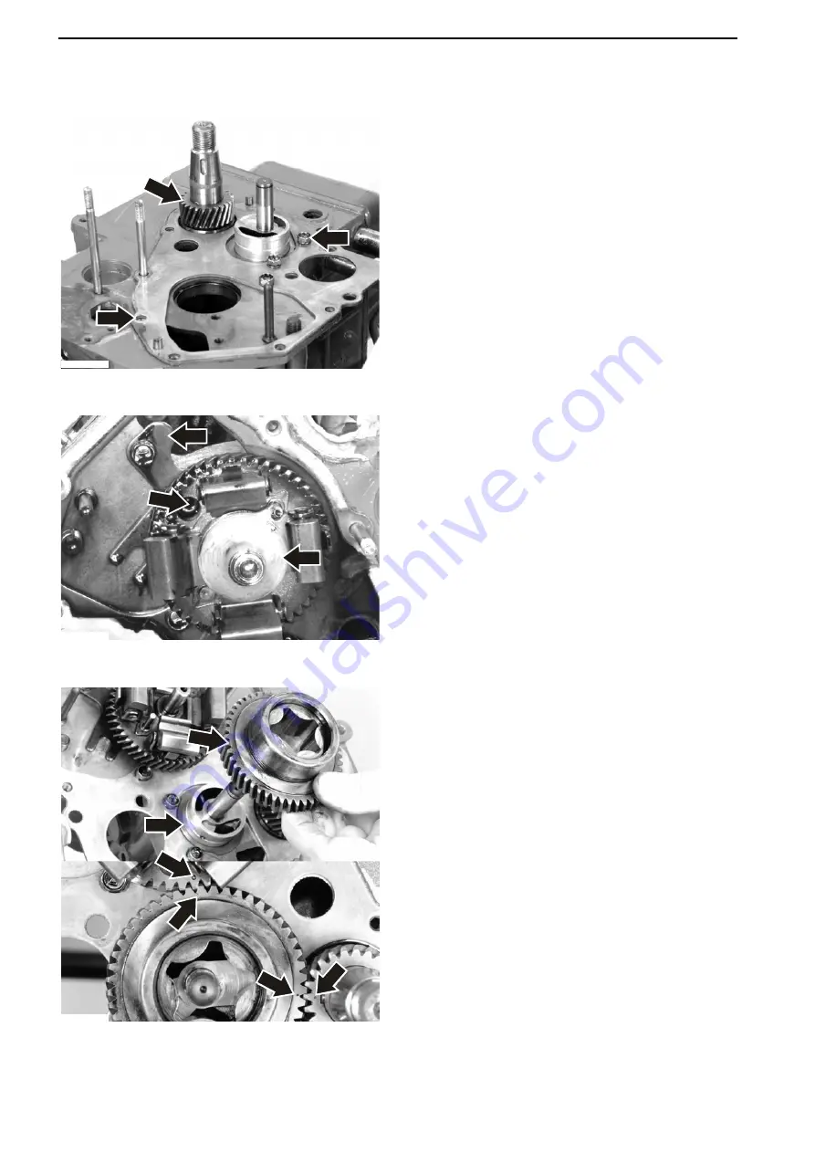
Timing Gear, Installation

Place the gear wheel (

1

) and its key on the crank-

shaft. Tap the gear wheel on.
Position the timing gear plate (

2

) and a new gas-

ket.
Fasten the timing gear plate inner bolts (

3

).

Carefully insert the camshaft.

IMPORTANT!

If the camshaft is forced in, there is a risk that one
of the cam lobes will damage an internal bearing.
Place the lock plate (

1

) in position. Rotate the cam-

shaft until the screw hole for the socket cap screw
(

2

) becomes visible in the hole in the camshaft

drive gear. Fasten the lock plate. Place the cam-
shaft regulator sleeve (

3

) in position.

Fit the thrust washing (

1

) in place. Put on the oil

pump gear wheel (

2

). Make sure that the mark-

ings (

3

) on the gear wheel line up with the mark-

ings (

4

) on the other gear wheels. Check the gear

flank play; refer to 

Flank Clearance, Check-

ing page 76

.

1

3

2

P0008044


1

3

2

P0008045


1

3

3

4

4

2

P0008046


21-5 Timing Gears and Shaft

80

47701798 05-2013  © AB VOLVO PENTA

Summary of Contents for D1-13

Page 1: ...Group 21 26 Workshop Manual 2 0 A D1 13 D1 20 D1 30 D2 40 ...

Page 2: ......

Page 3: ... General 49 Exposing the Engine 49 Fitting the Fixture 50 Engine Disassembly 51 21 1 Cylinder Head 55 21 2 Cylinder Block 64 21 3 Cylinder Liner Pistons 65 21 4 Valve Mechanism 70 21 5 Timing Gears and Shaft 76 21 6 Crank Mechanism 88 21 9 Miscellaneous 99 Lubricating and Oil System 22 1 Oil pump and Line 100 Fuel System 23 0 Fuel System General 101 23 3 Fuel Feed Pump and Filter 102 23 6 Injectio...

Page 4: ...32 1 Alternator 127 Starting System 33 1 Starter Motor 128 Alphabetical index 129 References to Service Bulletins 131 2 47701798 05 2013 AB VOLVO PENTA ...

Page 5: ...approved by Volvo Penta will be compensated by any warranty undertaking Certified engines When carrying out service and repair on emis sion certified engines it is important to be aware of the following Certification means that an engine type has been inspected and approved by the relevant authority The engine manufacturer guarantees that all engines of the same type are manufactured to correspond...

Page 6: ...that dirt and foreign objects are kept away as malfunctions or shortened service intervals may oth erwise result Our mutual responsibility Each product comprises a large number of interacting systems and components A deviation from the tech nical specification may dramatically increase the environmental impact of an otherwise reliable sys tem It is therefore critical that the stated wear toler anc...

Page 7: ... removed Old RTV sealant must be removed before the component is sealed again Use denatured alco hol Anaerobic agents These agents cure harden in the absence of air These preparations are used when two solid compo nents e g two cast components are fitted together without a gasket Common uses are also to lock and seal plugs stud threads taps oil pressure monitors etc Hardened anaerobic preparations...

Page 8: ...white Position P0015623 Focus arrows pointing at object Sometimes it con tains number of items e g three bolts NOTICE If an arrow with the text x3 is pointing at only one item e g a bolt it still applies to the other two alike items the two other bolts highlighted in the illustration P0015627 This symbol gives a positioning number to an object e g 2 which is also mentioned in the supplied text inf...

Page 9: ...show how many revolutions the object shall be turned and at which direction Tools P0015629 One of the following symbols is used when describing the recommended type of screwdriver Tools continuence P0015630 A symbol of a tool in a corner of the illustration is shown when the tool is recommended to use e g a knife or a crowbar P0015631 A drill in a specified size duck tape and stripes may also be s...

Page 10: ...ow thick layer of sealant to applicate The clock symbol is used when something needs to be done within or after a certain time Units P0015696 Units are mentioned in the illustration when a specific value e g pressure weight or resistance etc is expected Important P0015005 The eye symbol is used when something needs close inspection or must be performed in a certain way The symbol to the right is u...

Page 11: ... 20 A B F 93 Nm 68 6 lbf ft D1 30 A B F D2 40 A B F 123 Nm 90 7 lbf ft Flexible coupling 8 5 11 5 Nm 6 3 8 5 lbf ft Suction strainer oil pump 11 Nm 8 1 lbf ft Sump 11 Nm 8 1 lbf ft Drain plug sump 34 Nm 25 1 lbf ft Camshaft mounting screw for retainer plate 11 Nm 8 1 lbf ft Rocker arm shaft cover D1 13 A B F D1 20 A B F 9 5 Nm 7 0 lbf ft D1 30 A B F D2 40 A B F 23 Nm 17 0 lbf ft Valve Cover Mounti...

Page 12: ...7 Nm 12 5 lbf ft Fuel pump Adjuster screw 2 5 Nm 1 8 lbf ft Mounting screws 6 Nm 4 4 lbf ft Glowplugs 11 5 Nm 8 5 lbf ft Oil pressure contact and adapter 11 Nm 8 1 lbf ft Coolant temperature contact 27 Nm 19 9 lbf ft Coolant drain plug plastic 3 Nm 2 2 lbf ft Coolant thermostat housing 14 Nm 10 3 lbf ft Oil pressure relief valve 64 Nm 47 2 lbf ft Start motor contacts 9 8 11 8 Nm 7 2 8 7 lbf ft Gen...

Page 13: ...linder head D2 40 1 2 3 4 5 6 7 8 9 10 11 12 13 14 15 16 17 18 P0008160 D1 20 D1 30 1 2 3 4 5 6 7 8 9 10 11 12 13 14 P0008161 D1 13 1 2 3 4 5 6 7 8 9 10 P0008162 03 2 Specifications Engine 47701798 05 2013 AB VOLVO PENTA 11 ...

Page 14: ...76 Torque Nm lbf ft 0 738 lbf ft Nm 1 356 Pressure Bar PSI 14 5038 PSI Bar 0 06895 MPa PSI 145 038 PSI MPa 0 006895 Pa mm Wg 0 102 mm Wg Pa 9 807 Pa in Wg 0 004 in Wg Pa 249 098 kPa in Wg 4 0 in Wg kPa 0 24908 mWg in Wg 39 37 in Wg mWg 0 0254 Energy kJ kWh BTU hph 0 697 BTU hph kJ kWh 1 435 Work kJ kg BTU lb 0 430 BTU lb kJ kg 2 326 MJ kg BTU lb 430 BTU lb MJ kg 0 00233 kJ kg kcal kg 0 239 kcal kg...

Page 15: ...on ratio 23 5 1 23 5 1 23 1 23 5 1 Compression ratio at 250 rpm service limit 2 450 kPa 355 PSI Firing sequence highest cyl next to flywheel 1 2 1 2 3 1 2 3 1 3 4 2 Direction of rotation seen from front Clockwise Max forward incline 0 Max permissible rearward incline in operation 25 Max lateral incline in opera tion 35 Valve clearance idle cold engine inlet and exhaust 0 20 0 008 Weight dry engine...

Page 16: ...limit all engines 0 25 mm 0 010 Clearance between piston and cylinder D1 13 A B F D1 20 A B F 0 048 0 082 mm 0 0019 0 0032 D1 30 A B F D2 40 A B F 0 0525 0 0865 mm 0 0021 0 0034 Service limit all engines 0 25 mm 0 010 Front marking The designation SHIBAURA on the inside of the pis ton must face the fuel pump on installation 03 2 Specifications Engine 14 47701798 05 2013 AB VOLVO PENTA ...

Page 17: ...9 Oil ring Clearance between piston ring groove and ring all engines 0 02 0 06 mm 0 0008 0 0024 Service limit all engines 0 15 mm 0 0059 Piston ring gap D1 13 A B F D1 20 A B F 0 10 0 30 mm 0 0039 0 0118 D1 30 A B F D2 40 A B F 0 20 0 35 mm 0 0079 0 0138 Service limit all engines 1 0 mm 0 39 Piston pins Diameter D1 13 A B F D1 20 A B F 18 998 19 002 mm 0 7480 0 7481 Service limit 18 98 mm 0 7472 D...

Page 18: ... rocker arm shaft D1 13 A B F D1 20 A B F minimum permissible play 0 032 0 065 mm 0 00126 0 00260 D1 30 A B F D2 40 A B F minimum permissible play 0 032 0 068 mm 0 00126 0 00268 Maximum permissible play all engines 0 2 mm 0 008 Crankshaft Thrust bearings Standard thickness 21 85 21 95 mm 0 8602 0 8642 Service limit 21 60 mm 0 8504 NOTICE The thrust bearings are pressed into the main bearing retain...

Page 19: ...8858 3 47 954 47 965 mm 1 88800 1 88830 Service limit 47 90 mm 1 8858 NOTICE No undersize journal shells are available D2 40 A B F 1 2 and 3 47 965 47 975 mm 1 88830 1 88880 Service limit 47 90 mm 1 8858 4 47 954 47 965 mm 1 88800 1 88830 Service limit 47 90 mm 1 8858 NOTICE No undersize journal shells are available Clearance between bearing shell and journal standard play D1 13 A B F journal 1 0 ...

Page 20: ...39 0 092 mm 0 00150 0 00360 Service limit all engines 0 20 mm 0 0079 Con rods Piston pin bearing Clearance between piston pin and piston pin bearing 0 010 0 025 mm 0 00040 0 00099 Service limit D1 13 A B F D1 20 A B F 0 10 mm 0 004 Service limit D1 30 A B F D2 40 A B F 0 08 mm 0 0031 Connecting rod bearings Clearance between connecting rod bore and connecting rod bearing 0 10 0 30 mm 0 004 0 012 S...

Page 21: ... 27323 0 27362 Service limit 6 84 mm 0 269 Valve disc 0 925 1 075 mm 0 03642 0 04232 Service limit 0 5 mm 0 02 Valve depth beneath cylinder head plane 0 85 1 15 mm 0 0335 0 0453 Service limit 1 8 mm 0 071 Clearance valve guide 0 045 0 072 mm 0 0020 0 0030 Service limit 0 25 mm 0 0098 Seat angle in cylinder head 45 Seat contact surface in cylinder head 1 70 2 10 mm 0 0670 0 0830 Service limit 2 5 m...

Page 22: ...face 0 01 0 15 mm 0 0004 0 0059 Service limit 0 20 mm 0 0079 Shims available for adjustment of end float 0 10 0 15 0 20 0 50 mm 0 0039 0 0059 0 0079 0 0200 Oil grade according to API system VDS 2 ACEA E7 API CH 4 Viscosity at 5 to 50 C 23 F to 122 F SAE 15W 40 SAE 20W 50 Maximum oil volume excl oil filter no engine incline D1 13 A B F 1 9 l 0 50 US gals D1 20 A B F 2 8 l 0 74 US gals D1 30 A B F 3...

Page 23: ...22 1 Pump element diameter 5 mm 0 1968 5 mm 0 1968 6 mm 0 2362 5 5 mm 0 2165 Stroke 6 5 mm 0 2559 6 5 mm 0 2559 6 mm 0 2362 6 mm 0 2362 Injectors Opening pressure at checks D1 13 A B F D1 20 A B F 11 96 MPa 1735 PSI D1 30 A B F 13 9 MPa 2016 PSI D2 40 A B F 14 7 MPa 2132 PSI Jet angle 4 Exhaust System Max permissible exhaust back pressure in exhaust line at max rpm all engines 20 kPa 2 9 PSI 03 2 ...

Page 24: ... starts opening at 90 C 194 F fully open at 105 C 221 F Coolant conc coolant water mixture 40 60 Water Quality ASTM D4985 Total solid particles 340 ppm Total hardness 9 5 dH Chloride 40 ppm Sulfate 100 ppm pH value 5 5 9 Silica acc ASTM D859 20 mg SiO2 l Iron acc ASTM D1068 0 10 ppm Manganese acc ASTM D858 0 05 ppm Conductivity acc ASTM D1125 500 µS cm Organic content CODMn acc ISO8467 15 mg KMnO4...

Page 25: ... 40 A B F 88 Ah Glowplugs rated voltage 11 V current 11 A Alternator Output voltage at 20 C 68 F with sense 14 2 0 15 V without sense 14 2 0 30 V Max current 115 A Power approx 1 630 W Suppression capacitor 2 2 μF Starter motor Power approx D1 13 A B F D1 20 A B F 0 8 kW D1 30 A B F 1 1 kW D2 40 A B F 1 4 kW 03 3 Specifications Electrical 47701798 05 2013 AB VOLVO PENTA 23 ...

Page 26: ...WARNING Indicates a hazardous situation which if not avoided could result in death or serious personal injury CAUTION Indicates a hazardous situation which if not avoided could result in minor or moderate personal injury IMPORTANT Is used to draw your attention to something that may cause minor damage or a minor malfunction to the product or property NOTICE Is used to draw your attention to import...

Page 27: ...r bocharger can cause severe injury Foreign objects entering the intake ducts can also cause mechanical damage Install all protective cov ers before the engine is started Ensure that the warning symbols or information decals on the product are always clearly visible Replace decals which have been damaged or painted over Only start the engine in a well ventilated space When running in a confined sp...

Page 28: ...A spark which can be caused by incorrect battery connection is sufficient to cause a battery to explode and cause damage Do not touch the connections during start attempts Sparking hazard Do not lean over batteries Never work alone when removing heavy com ponents even when using lifting devices such as locking tackle lifts When using a lifting device two people are usually required to do the work ...

Page 29: ...the Operator s Manual for the product in question Use of fuels that are of a lower grade may damage the engine the injection pump and the injectors On a diesel engine low grade fuel can cause the control rod to bind and the engine to over rev with the risk of engine damage and personal injury as a result Low fuel and oil grades may result in high service maintenance and repair costs Never use a hi...

Page 30: ...ed for compressing valve springs Used for installation of engine in 9992520 Stand or 9986485 Stand with the aid of 9999737 Fixture P0007806 P0007568 885252 Adapter 885484 Adapter 885498 Adapter Used for compression testing Used for compression testing Floor lock used together with 885023 Valve spring compres sor rig O in a l P0002936 P0007816 P0004343 885510 Plugs 885820 Puller 885822 Magnetic pen...

Page 31: ...ixture Holder for 9989876 Dial indica tor P0007809 P0006804 9995919 Extractor 9996662 Pressure testing kit 9998699 Break out box Used for seals Used for checking pressure valve in filler cap Used for measuring P0001878 2 0 1 0 0 0 2 0 P0001881 P0001879 9999179 Extractor oil filter 9999683 Dial indicator short probe 9999696 Magnetic stand Wrench for removing fuel and oil filters Used when checking ...

Page 32: ...nder used for 885224 Fixture to 9986485 Stand Used for checking injectors Used for oil pump shaft D1 13 D1 20 P0007813 p0005128 3849640 Mounting tool 88890016 Break out cable Used for oil pump shaft D1 30 D2 40 For use with 9998699 Break out box 08 2 Special Service Tools 30 47701798 05 2013 AB VOLVO PENTA ...

Page 33: ...nce and location of the type plates is shown below The figures in brackets refer to the location of the identification number on the type plate Engine P0007541 A B C Product designation 1 Product number 2 Serial number 3 Transmission Product designation 4 Gear ratio 5 Serial number 6 Product number 7 A Engine and transmission decal B Engine plate C Transmission plate p0007825 A A B C 20 0 Engine I...

Page 34: ...n line four cylinder engine with a total swept volume of 1 51 liter The D1 13 and D1 20 engines have identical pistons with the same dimensions The D1 30 and D2 40 engines have different pistons but of common dimen sions The engines are lubricated by a pressure lubrication system in which an oil pump supplies oil under pres sure to all lubrication points Fresh water cooling uses a thermostatically...

Page 35: ...D1 13 with MS10A reverse gear D1 20 with MS10A reverse gear 20 0 Engine Information General 47701798 05 2013 AB VOLVO PENTA 33 ...

Page 36: ...D1 30 with MS15A reverse gear D2 40 with 130S sailboat drive 20 0 Engine Information General 34 47701798 05 2013 AB VOLVO PENTA ...

Page 37: ...om special cast iron alloy The cylinder head has one inlet and one exhaust valve per cylinder These are operated by the camshaft via valve lifters and push rods The valves have replace able seats An injector is installed in the combustion chamber of each cylinder There is one glowplug per cylinder Rocker arm cover The rocker arm cover 2 is aluminum and is located above the cylinder head The valve ...

Page 38: ...ecting rods 8 are of I section The small end is drilled for piston pin lubrication Pistons The pistons 9 are made of light metal alloy They have three piston rings 10 Two piston rings are com pression rings and one is an oil ring Transmission The timing gear comprises cylindrical gear wheels with helical cogs and is located at the front of the cylinder block A timing gear cover 1 provides complete...

Page 39: ...con trolled with a valve and spring located in the valve cover When the gas pressure is higher the valve opens and directs the crankcase gases into the inlet section for combustion in the cylinders P0007836 20 0 Engine Information General 47701798 05 2013 AB VOLVO PENTA 37 ...

Page 40: ... The lubrication system has a relief valve which limits the maximum oil pressure in the engine The oil filter is of full flow type and is fitted with an overflow valve 1 2 3 4 5 6 7 8 P0007818 1 Oil filter 2 Oil pressure monitor 3 Pressure relief valve 4 Inlet pipe with strainer 5 Main oil duct 6 Oil pump 7 Oil delivery pipe outer to valve mechanism 8 Crankcase ventilation valve 20 0 Engine Inform...

Page 41: ... Oil pump The lubrication pump is located within the idler gear on the timing gears by which it is also driven The pump is a rotor pump with an inner rotor and an outer rotor mounted eccentrically in relation to each other The inner rotor has one tooth less than the outer rotor Pump function results from the space between the inner and outer gear wheels increasing and decreas ing During the first ...

Page 42: ...s filtered before it is forced out into the lubrication system The filter element consists of folded filter paper There is a bypass valve 1 at the base of the filter which opens and allows oil to flow past the filter ele ment if the filter insert should become blocked 1 P0007860 20 0 Engine Information General 40 47701798 05 2013 AB VOLVO PENTA ...

Page 43: ...injectors is returned to the base of the fuel tank Air in the fuel system can be transported back to the fuel tank via a connection between the injection pump and the return fuel pipe The fuel is then forced at high pressure through the injector nozzles into a pre combustion chamber in the cylinder head and then enters the piston combustion chamber where an air vortex contributes to even combustio...

Page 44: ... governed throughout the entire range from low idle to high idle all speed type Injectors The engine is provided with pintle type injectors Each injector basically consists of a nozzle retainer and a nozzle When the fuel pressure increases to the set value opening pressure the injector needle which is held pressed against its seat by the compression spring is lifted and atomized fuel is injected i...

Page 45: ...tric on the rear of the camshaft Fuel Filter The fuel filter 1 is of the disposable type The filter insert is a paper filter The fuel filter is located in a bracket 2 together with a hand pump 3 and vent screw 4 P0007865 P0007866 20 0 Engine Information General 47701798 05 2013 AB VOLVO PENTA 43 ...

Page 46: ... risk of boiling if the temperature becomes high If the pressure becomes higher than normal a pressure valve opens in the filler cap on the expansion tank The coolant temperature is regulated by a thermostat When the engine is cold a thermostat directs the coolant round an internal circuit in the engine When operating temperature begins to be reached the cool ant is progressively directed out thro...

Page 47: ... Refer to Group 26 Cooling System page 22 for open ing temperatures The thermostat is located in a housing which is inte grated in the heat exchanger and exhaust manifold Coolant Pump The coolant pump is mounted on the engine block and is driven by the crankshaft by means of a drive belt Seawater Pump The raw water pump is a rubber impeller type pump mounted on the front of the engine The pump is ...

Page 48: ...h the heat exchanger matrix and transfers heat from the internal cooling circuit in the engine fresh water system to the outer circuit raw water When the thermostat is closed coolant is led through a short uncooled passage in the heat exchanger and back to the engine P0007940 20 0 Engine Information General 46 47701798 05 2013 AB VOLVO PENTA ...

Page 49: ...uel system Plug the connections for the disassembled injectors and fuel pipes The compression pressure must be read at normal starter motor speed Low combustion pressure in all cylinders indicates worn cylinder bores and piston rings If one cylinder has lower compression than the others the reason can be poor valve sealing broken piston rings or a dam aged cylinder head gasket Place the adapters 8...

Page 50: ...e of the engine NOTICE Make sure that wash residue is col lected for destruction and does not inadvertently end up in the environment IMPORTANT Remember the following when washing with a power washer Be extremely careful when clean ing to avoid getting water inside engine compo nents When a power washer is used the water jet must never be aimed at seals such as shaft seals joints with gaskets rubb...

Page 51: ...Undo the propeller shaft from the reversing gear Undo the engine mounting pads from the bed and lift the engine out Use the lifting lugs 1 on the engine Actions after lifting the engine 1 Clean the engine IMPORTANT Remember the following when washing with a power washer Be extremely careful when cleaning to avoid getting water inside engine components When a power washer is used the water jet must...

Page 52: ...92520 Stand Use 885224 Fixture and 9999737 Fixture to secure the engine in 9986485 Stand Only 885224 Fixture is required for securing in 9992520 Stand Bolt the fixture to the right side of the engine as illus trated D1 13 A B F P0007974 D1 20 A B F P0007975 D1 30 A B F P0007976 D2 40 A B F P0007977 21 0 Engine Complete General 50 47701798 05 2013 AB VOLVO PENTA ...

Page 53: ... with brackets 3 Remove the electronics box 4 together with the cable harness Undo the engine rpm sensor 5 NOTICE Note the way that the cable harness is clamped before removing it 4 Remove the alternator 6 with bracket starter motor 7 and the left side engine mounting 8 5 Remove the heat exchanger exhaust manifold 9 raw water pump 10 coolant pump 11 with spacer D1 13 6 Remove the oil pressure moni...

Page 54: ...olts Turn the stop lever clockwise and carefully lift the pump to make the lock clip on the regulator arm accessible Remove the lock clip 23 and free the governor arm 24 IMPORTANT Be careful when disassembling the injection pump avoid damaging or bending its lever NOTICE Retain the shim gasket 25 located beneath the injection pump flange Use the same thickness of shims when installing 11 Remove th...

Page 55: ...fters from the cylinder block using 885822 Magnetic pen If the valve lifters are to be re used they must be replaced in their orig inal positions NOTICE The D1 20 and D2 40 engines have certain valve lifters that are beveled 16 Remove the flywheel housing 33 and oscillation damper 34 17 Undo the center nut 35 on the pulley Remove the pulley 36 use special tool 885820 Puller Use the flywheel as a c...

Page 56: ...urn the engine upside down and remove the sump together with the external oil pipe Remove the oil strainer 45 and the oil suction pipe 46 Remove the oil relief valve 25 Scrape away the line of carbon at the top of the cylinders to facilitate removal Remove the big end bearing caps 47 and press the pistons out NOTICE Check the markings on the big end bearing caps 26 Remove the locking screws 48 tha...

Page 57: ... found the cylinder head must be changed If leakage is found or if the cylinder head has blow lines no special meas urement is needed since such a cylinder head will have to be attended to in any case Check the valve seats and check that the studs are firmly seated Inspect the cylinder head for cracks Carefully check the areas around the valve seats and the holes for the injector nozzles A B C D E...

Page 58: ...od crankshaft or engine block has been changed new meas urement must be done 4 Dip the cylinder head bolts in engine oil and leave them to run off on a strainer The bolts should have stopped dripping when they are installed otherwise oil might well up and be regarded as leakage IMPORTANT The bolts are phosphated and must not be cleaned with a steel wire brush If the cylinder head is painted the co...

Page 59: ...quence and torque in Tightening torques page 9 Re tighten all bolts 7 Install the glowplugs 4 and current bar 5 8 Install the push rods 6 valve caps 7 and rocker arm mechanism 8 with gasket Torque the nuts 9 refer to Tightening torques page 9 5 3 4 P0008071 6 7 9 8 P0008072 21 1 Cylinder Head 47701798 05 2013 AB VOLVO PENTA 57 ...

Page 60: ...g torques page 9 13 Install the hollow screw 16 on the injection pump and the banjo nipple with new copper washers 14 Install new copper gaskets and install the return fuel line 17 Tighten the nuts and connect the return line 15 Install the delivery pipes 18 For tightening tor ques refer to Tightening torques page 9 16 Install the coolant pump 19 with spacer D1 13 A B F and a new gasket 17 Clean t...

Page 61: ...3 together with the front engine mounting 34 24 Install the expansion tank and attachment fitting 35 25 Connect all coolant hoses 36 Tighten all hose clamps and brackets 26 Install the electronics box 37 with cable har ness connect the connectors and other electrical connections Clamp the cable harness as previ ously noted 27 Install the induction silencer 38 28 Remove the engine fixture and insta...

Page 62: ...s 1 Undo and remove the return fuel pipe 2 IMPORTANT Seal all openings in the fuel system with protective caps 3 Undo the oil supply pipe 1 at the cylinder head Unscrew the injectors 2 IMPORTANT Seal all injector openings with caps Unscrew the nuts 3 which hold the rocker arm bridge The D1 20 D1 30 and D2 40 engines also have bolts that must be removed Carefully prise the rocker arm bridge loose 1...

Page 63: ...d valve caps 2 Mark them Undo the cylinder head bolts 3 in reverse tight ening sequence refer to Tightening tor ques page 9 Remove the cylinder head and gas ket 1 3 2 P0008093 21 1 Cylinder Head 47701798 05 2013 AB VOLVO PENTA 61 ...

Page 64: ... are in place 2 Check that the engine block guide pins for the cylinder head are in place Install a new cylinder head gasket with the marking upwards Put the cylinder head in place Insert the bolts 1 and torque them according to the tightening sequence and to the specific torque refer to Tightening torques page 9 3 Put the push rods 1 and valve caps 2 in place P0008070 1 1 P0008077 1 2 1 P0008078 ...

Page 65: ...ing torques page 9 5 Install the oil delivery pipe 1 on the cylinder head with new seals 6 Installing the injectors Apply sealant part no 840879 to the two lowest threads 1 Put new copper seals on the bottom of the cylinder head Install the injectors and tighten them evenly to the specified torque refer to Tightening tor ques page 9 2 1 3 P0008079 2 1 P0008080 P0008084 1 21 1 Cylinder Head 4770179...

Page 66: ...inder bore Check that the cylinder bores are not scored or dam aged in other ways Measure the cylinder bores at the piston ring top and bottom dead center positions approx 10 mm 0 39 and 100 mm 3 94 below the engine block plane and also in between Measurement should be done with an internal dial gauge both longitudinally and transversely to the engine block A and B Concerning max permitted cylinde...

Page 67: ... time when a piston ring change should be done 5 Check the clearance in the piston ring grooves Rotate the ring in its piston groove and measure the clearance at several points with a feeler gauge Refer to Group 21 Engine page 14 for measurements Piston and Cylinder Bore Inspection and Measurement Check the pistons for cracks and worn piston ring grooves Change the piston if it has deep lines in t...

Page 68: ...nscrew the oil suction strainer 1 Remove the suction pipe 2 with its O ring Unscrew the connecting rod bearing caps 3 IMPORTANT Note the markings on the bearing caps and their locations 3 Press the pistons out NOTICE There may be a soot deposit on the top of the cylinder bores Remove the deposit to facil itate pressing the pistons out 1 2 3 P0008094 1 2 3 P0008095 21 3 Cylinder Liner Pistons 66 47...

Page 69: ...e piston pin bushing and check it 3 Install a new piston in the correct position Press the piston pin in Install the retainer rings with the lugs facing upwards Big end bearing change Pistons removed 1 Remove the big end bearings 1 and put the new ones in position 1 1 2 P0008096 1 P0008097 21 3 Cylinder Liner Pistons 47701798 05 2013 AB VOLVO PENTA 67 ...

Page 70: ...ert the piston 1 in the bore and carefully tap it down The piston marking SHIBAURA must face the injection pump side IMPORTANT Make sure that the connecting rod studs to not strike the crankshaft when tapping down the pis ton 3 Install the big end bearing cap according to the mark Tighten with 23 Nm of torque 17 0 lbf ft D1 13 D1 20 or 32 Nm 23 6 lbf ft D1 30 D2 40 Check the movement of the big en...

Page 71: ... IMPORTANT Make sure that the connecting rod studs to not strike the crankshaft when tapping down the pis ton The connecting rod with the lowest number must be installed at the front in cyl no 1 and the con necting rod with the highest number closest to the flywheel The connecting rods must be turned so that the mark number color mark is facing towards the injection pump camshaft side 4 Install th...

Page 72: ...ap Then crank the engine exactly one more turn Adjust the valves for no 2 cylinder D1 20 D1 30 Crank the engine clockwise until the valves for no 1 cylinder overlap Adjust no 2 inlet valve 1 and no 3 exhaust valve 2 Refer to item 3 for the adjustment procedure Crank the engine clock wise until the valves for no 2 cylinder overlap Adjust no 3 inlet valve 3 and no 1 exhaust valve 4 Crank the engine ...

Page 73: ...ves for no 3 cylinder overlap Adjust no 2 inlet and exhaust valve D 3 Adjustment Undo the locknut 1 with a ring wrench Measure the valve clearance 2 with a feeler gauge Adjust the valve clearance with the adjustment screw 3 The correct valve clearance for all valves and engines is 0 2 mm 0 0079 When the correct valve clearance has been reached tighten the locknut 1 4 Install the valve cover with a...

Page 74: ...nstallation Tools 885023 Valve spring compressor 885498 Adapter 1 Install the valve 1 in the cylinder head as marked Install a new valve seal 2 spring 3 and valve spring washer 4 Compress the valve spring with the spring clamp and install the collets 5 2 Install the glowplugs and tighten to the specified torque refer to Tightening torques page 9 Install the busbar 1 2 3 P0008146 885 498 885 023 P0...

Page 75: ...lve about 2 mm 0 08 from its seat put the measurement tip on the valve seat rim and check the wear Permissible clearance between valve and valve guide Inlet valve max clearance 0 20 mm 0 008 Exhaust valve max clearance 0 25 mm 0 010 NOTICE Since the valve guides are machined directly in the cylinder head the cylinder head must be changed when the clearance is too great even when the valve is new P...

Page 76: ...alve seats are machined 4 Mill the valve guides When machined only remove enough material to give the valve seat the correct shape and a good mating surface NOTICE Do not grind so much that the valve depth exceeds the permissible value Please refer to Valve Seat Change page 75 Mill new seats down so far that the distance between the cylinder head plane and the valve disc surface B is between 0 65 ...

Page 77: ...raulic press and a suitable mandrel 5 Machine the seats to the correct angle and width Rocker Arm Mechanism Overhaul 1 Remove the plug at the front of the rocker arm shaft If the shaft has a stop screw it must be removed before the shaft is pulled out 2 Disassemble the rocker arm mechanism Remove the rocker arms springs and washers 3 Clean the components Be especially careful with the rocker arm s...

Page 78: ...measure the flank clearance 2 between the oil pump gear and the crankshaft gear Refer to Group 21 Engine page 14 for min and max values Timing Gear Removal Cylinder head removed Tools 885820 Puller 885822 Magnetic pen 1 Remove the raw water pump 1 Remove the end panel 2 and the bolts 3 1 2 P0008038 1 2 3 P0008050 21 5 Timing Gears and Shaft 76 47701798 05 2013 AB VOLVO PENTA ...

Page 79: ...the groove in the shaft 3 Unbolt the injection pump 1 Lift it up until the lock clip 2 is accessible Undo the clip and release the control rod 3 4 Undo the timing gear cover bolts 1 and nut 2 Remove the cover 885 820 P0008082 1 2 3 P0008083 2 1 P0008084 21 5 Timing Gears and Shaft 47701798 05 2013 AB VOLVO PENTA 77 ...

Page 80: ...ifters that are beveled 7 Rotate the camshaft until the socket cap screw 1 is visible in the hole in the camshaft drive gear Unscrew the socket cap screw and hex head bolt 2 Remove the lock plate 3 Remove the camshaft regulator sleeve 4 Pull the camshaft out carefully IMPORTANT There is a risk of damaging the inner camshaft bearing with a camshaft lobe if the camshaft is pulled out with force 2 1 ...

Page 81: ...ote the spacer washer 2 inside the oil pump gear 9 Undo the remaining bolts 1 Remove the timing gear plate 2 Remove the crankshaft gear 3 with a puller Remove the gear wheel and its Woodruff key 2 1 P0008088 2 3 1 P0008089 21 5 Timing Gears and Shaft 47701798 05 2013 AB VOLVO PENTA 79 ...

Page 82: ...1 in position Rotate the cam shaft until the screw hole for the socket cap screw 2 becomes visible in the hole in the camshaft drive gear Fasten the lock plate Place the cam shaft regulator sleeve 3 in position 3 Fit the thrust washing 1 in place Put on the oil pump gear wheel 2 Make sure that the mark ings 3 on the gear wheel line up with the mark ings 4 on the other gear wheels Check the gear fl...

Page 83: ... Put the control rod 1 on the heel 2 in the timing gear cover Turn the stop arm 3 round so that the control rod is held against the heel 6 Install the timing gear cover at the same time as the control rod 1 is held fast by the stop arm 2 Put the timing gear cover in place Make sure that the control rod ends up in the correct position and that the pin 3 engages in the hole 4 in the oil pump end was...

Page 84: ...nkshaft Install the pulley and tighten it to the specified torque with the center nut refer to Tightening tor ques page 9 9 Put the valve lifters in place as marked IMPORTANT All valve lifters must be put back in their previous places Note that on D1 20 engines valve lifter no 2 for cylinder 1 has a chamfer 1 Note that on D2 40 engines both valve lifters for cylinder 1 have a chamfer 1 2 3 P000805...

Page 85: ...late 3 in the correct position and tighten it 4 Fit the key into the crankshaft and install the crankshaft gear 4 IMPORTANT The components must be oiled before installation IMPORTANT Make sure that the gear wheel markings coincide 5 Install the thrust washer 5 on the idler wheel shaft stub Install the idler wheel 6 in accord ance with the markings NOTICE Do not turn the crankshaft before the timin...

Page 86: ...ted in the timing cover and is connected to the regulator arm 18 Put the timing gear cover in place Insert the regulator arm through the hole in the cylinder block Bolt on the timing gear cover 10 Turn the stop arm 19 clockwise and connect the arm 20 to the injection pump Install the clip 21 NOTICE Carefully ensure that the shim gasket which was placed underneath the injection pump flange is put b...

Page 87: ...shaft and valve lifters do not have large pitting defects Pitting defects can occur for various reasons The defects are caused when small pieces of metal loosen from the hardened surface Lifters and camshafts with minor pitting defects may be used Pitting defects seldom becomes worse Check that the camshaft bearing surfaces and cam curves are not abnormally worn Change the camshaft if major damage...

Page 88: ...ive influence on either engine per formance or the durability of the engine and its com ponents Examples of acceptable wear and unacceptable wear are shown below Acceptable wear Unacceptable wear The camshaft does not need to be changed NOTICE The camshaft and associated rocker arms must be changed P0003896 P0003898 P0003899 P0003897 21 5 Timing Gears and Shaft 86 47701798 05 2013 AB VOLVO PENTA ...

Page 89: ...it Clean and check the crankshaft seal 3 Carefully clean the crankshaft and flywheel Install the new flywheel and tighten it to the speci fied torque refer to Tightening torques page 9 Install the flexible coupling flywheel housing fil ter housing bracket and engine rpm sensor 2 1 3 P0008104 1 P0008105 21 5 Timing Gears and Shaft 47701798 05 2013 AB VOLVO PENTA 87 ...

Page 90: ...gth 4 Check the end float between the connecting rod and crankshaft Change the connecting rod if the end float exceeds 0 035 0 085 mm 0 0014 0 0033 Also check the connecting rod bushes For per missible clearance between the piston pin A and the connecting rod bush B refer to Group 21 Engine page 14 Changing the piston pin bushing 1 Press the old bush out 2 Press the new bush in NOTICE Make sure th...

Page 91: ...n must face the same direction Slide the piston pin in NOTICE It should be possible to press the piston pin in easily It must not be driven in 4 Install the other retainer ring 5 Check that the connecting rod is not tight on the piston pin bearing 6 Check the big end bearing clearances Refer to Crankshaft and Bearings Inspection page 90 7 Check the piston ring gap in the cylinder bore and that the...

Page 92: ...ction Clean the crankshaft carefully in all channels after dis assembly and inspect the crankshaft thoroughly to determine if overhaul is really necessary 1 Check wear and ovality with a micrometer Meas ure the diameters A A and B B at points 1 and 2 Max permissible taper and ovality in the main and big end journals is 0 05 mm 0 002 Change the crankshaft if these values are exceeded 2 Measure long...

Page 93: ...the bearing journal outer diameter and calculate the bearing play difference between pre vious measurement and max diameter of the bear ing journal For max bearing play refer to Group 21 Engine page 14 Change the bush if the clearance exceeds the per missible value Inspection of main and big end bearings Check the main and big end bearing shells and the front main bearing bushing Change worn beari...

Page 94: ...arkings and tighten the connect ing rod bolts For tightening torques refer to Tightening tor ques page 9 NOTICE Do not rotate the connecting rod or crankshaft during measurement as this will destroy the measurement strip 3 Remove the big end cap and measure the width of the compressed plastigauge at the widest point Use the scale supplied with the plas tigauge For max permissible big end bearing p...

Page 95: ...ng caps together for tightening tor que refer to Tightening torques page 9 5 Carefully lift the crankshaft into place in the cyl inder block Align the main bearing holder bolt holes 1 before the crankshaft is pressed into place NOTICE Tape the crankshaft gear before lifting the crankshaft into place to prevent the gear teeth from damaging the front bearing seat 6 If necessary carefully tap the cra...

Page 96: ... crankshaft seal 1 3 Unscrew the oil pressure relief valve 4 Undo the bolts 1 that hold the main bearing caps Lift the crankshaft out NOTICE Tape the crankshaft gear teeth to pro tect the bearing when the shaft is pulled out 1 P0008101 1 P0008102 1 1 1 P0008103 21 6 Crank Mechanism 94 47701798 05 2013 AB VOLVO PENTA ...

Page 97: ...0 D1 30 and D2 40 engines must be care fully noted to avoid faulty replacement Also note the oil holes 3 in the bearing caps 2 Drive out the main bearing bush 1 located in the engine block Use a suitable mandrel and tap the bush out from inside the crankcase D1 20 D1 30 P0008098 1 1 1 2 3 3 3 D2 40 P0008029 1 P0008099 21 6 Crank Mechanism 47701798 05 2013 AB VOLVO PENTA 95 ...

Page 98: ... oil holes 3 must face the correspond ing holes in the engine block 5 Install the main bearing bush 1 in the cylinder block IMPORTANT Position the bush so that its oil hole is correctly aligned in the cylinder block The oil groove 2 in the bush must be furthest in Tap the bush in with a suitable mandrel 3 until it lines up with the cylinder block Check that the oil duct is open after pressing in t...

Page 99: ...d seal surfaces Tape over the key groove on the crankshaft to avoid damaging the new seal during installation 3 Lubricate the new crankshaft seal with engine oil and put it on the crankshaft Drive the seal into place with a suitable mandrel Remove the tape 4 Install the belt pulley key on the crankshaft Install the belt pulley and tighten it to the fasten it with the center nut to the specified to...

Page 100: ...seal on the engine block the crankshaft and the inner fly wheel housing are cleaned Lubricate the new crankshaft seal lip with engine oil and put the seal in place Apply sealant part no 840879 all round the crank shaft seal 2 and the camshaft cover 3 Fix the inner flywheel plate 1 P0008101 2 3 1 P0008106 21 6 Crank Mechanism 98 47701798 05 2013 AB VOLVO PENTA ...

Page 101: ...he drive belt Remove the drive belt 2 Install a new drive belt Tension the belt with the tensioner bolt Check the tension Tighten the alternator retaining nut and retaining bolts WARNING D1 30 D2 40 Ensure that the alter nator belt is placed in the groove closest to the alternator 2 3 1 1 P0008114 P0008115 D1 30 D2 40 21 9 Miscellaneous 47701798 05 2013 AB VOLVO PENTA 99 ...

Page 102: ...9640 Mounting tool for D1 30 and D2 40 First screw the guide pin 1 for the tool into the cylinder block Then put the new oil pump bearing 2 into the tool block 3 NOTICE It is important that the engine block sur face touching the tool is clean and smooth The tool block must be oiled 3 Position the tool block with the bearing in place using the guide pin Tap the bearing into place until the tool bot...

Page 103: ... needs to be changed 2 Operate the hand pump 2 located on the fuel filter bracket until fuel with no air bubbles comes out of the bleed screw Keep pumping at the same time as the bleed screw is closed Pump another 10 strokes 3 Wipe dry the fuel that runs out Start the engine and check sealing 1 2 P0008140 23 0 Fuel System General 47701798 05 2013 AB VOLVO PENTA 101 ...

Page 104: ...Hand Pump Change 1 Put a rag under the filter housing bracket to collect spilled fuel Undo the fine filter 1 it must be sorted as environmentally hazardous waste Undo the fuel unions 2 Unbolt the hand pump 3 and remove it 2 Put a new fine filter in the new hand pump Install the hand pump on the bracket Fasten the fuel unions Bleed the fuel system refer to Fuel system bleeding page 101 P0008138 1 2...

Page 105: ...d return fuel pipe 4 IMPORTANT Seal all openings in the fuel system with protective caps 2 Unbolt the injection pump 1 Lift it up until the lock clip 2 is accessible Undo the clip and release the control rod 3 Lift the injection pump out and remove the shim 1 2 3 4 P0008133 1 2 3 P0008083 23 6 Injection Pump Regulator 47701798 05 2013 AB VOLVO PENTA 103 ...

Page 106: ...of the studs 2 Tighten the injection pump to the specified torque refer to Tightening torques page 9 Install the feed line 3 4 Install the stop solenoid 1 with a new seal Install the fuel return pipe 2 Install the delivery pipes 3 and tighten to the specified torque refer to Tightening tor ques page 9 P0008134 1 2 3 1 3 2 P0008135 23 6 Injection Pump Regulator 104 47701798 05 2013 AB VOLVO PENTA ...

Page 107: ...NT Seal all openings in the fuel system with protective caps 2 Install the new injectors with new copper seals Apply sealant part no 840879 to the two lowest threads 1 For tightening torques refer to Tight ening torques page 9 Install the return fuel pipe use the nut underneath the fuel return pipe as a counterhold to avoid kinking the pipe Install the fuel delivery pipes Check that they do not co...

Page 108: ...inated magnifier or an injector microscope Also check the other components 5 When installing a new nozzle it is important that the conserving oil is cleaned off the injector nee dle and sleeve before the injector is assembled avoid skin contact with the needle s sliding sur face Clean the components in chemically pure white benzene Check that the needle slides in the sleeve with no tendency to bin...

Page 109: ...a change of shim thickness of 0 1 mm 0 0039 Checking injectors Spray pattern Tools 9999772 Pressure testing kit 1 Pump the injector tester special tool 9999772 Pressure testing kit and check the injector spray pattern The fuel spray should be cone shaped and aligned with the injector center line Fuel drops must not occur in the spray 2 Check that the fuel jet has a circular cross section Sealing W...

Page 110: ...speed with a tachometer refer to Group 23 Fuel Sys tem page 21 for correct idling speed 3 Use adjustment screw 2 as necessary to give the correct idling speed 4 Check the gap 3 again as in item 1 Race revolutions high idle Warm the engine up and check the race revolutions with a workshop tachometer when the engine is unloaded at full throttle refer to Group 23 Fuel Sys tem page 21 for correct race...

Page 111: ... Volvo Penta engines and offer excellent protection against corrosion cavitation damage and bursts due to freezing Only coolants of this quality are adapted to and approved by Volvo Penta We recommend that the coolant supplied with the engine on delivery be used Future warranty claims related to engine and accessories may be declined if an unsuitable coolant has been used or if the instruc tions f...

Page 112: ...ure protects against internal corrosion cavi tation and bursts due to freezing down to 28 C 18 F A 60 glycol admix lowers the freezing point to 54 C 65 F Never mix more than 60 concentrate in the coolant A greater concentration provides reduced cooling effect with the risk for overheating and reduced anti freeze protection It is extremely important that the system be filled with the correct coolan...

Page 113: ...sh the cooling system clean before new coolant is added Close all drain points and fill up with coolant to the cor rect level The engine must be stopped when the cooling sys tem is filled and must not be started until the sys tem is vented and completely filled If a heating installation is connected to the engine cooling system the heat control valve must be fully open and the instal lation vented...

Page 114: ... temperature Excessive coolant temperature warning lamp lights up can be caused by Blocked raw water inlet or raw water filter Defective impeller in the raw water pump Too low coolant level air in the fresh water system Slipping or broken coolant pump vee belt Faulty thermostat temperature sensor or gauge Blocked cooling system Incorrectly set injection advance in the injection pump Filler cap gas...

Page 115: ...the drain hose from the filler pipe with a hose that discharges into a water filled vessel 3 Increase the pressure and read the pressure gauge when the valve opens water bubbles into the vessel with the drain hose The valve should open at 75 kPa 10 9 PSI 4 Remove the test equipment Install the plug and fill the engine with coolant P0002790 26 0 Cooling System General 47701798 05 2013 AB VOLVO PENT...

Page 116: ... fitting D1 30 and D2 40 1 Undo the heat exchanger end plate on the alter nator side Remove the exhaust elbow 1 and hose clamp 2 from the heat exchanger end plate Remove the exhaust elbow Undo the other heat exchanger end plate 3 2 Remove the insert 1 and clean it P0008143 3 2 1 1 p0008144 26 1 Radiator Heat Exchanger 114 47701798 05 2013 AB VOLVO PENTA ...

Page 117: ...e end plate onto the heat exchanger 4 Install new O rings 2 on the insert and end plate Bolt the end plate onto the heat exchanger Install the exhaust elbow 5 Fill up with coolant Check the level and sealing after warming up 1 2 P0008145 26 1 Radiator Heat Exchanger 47701798 05 2013 AB VOLVO PENTA 115 ...

Page 118: ...away Remove the gasket 3 Clean the sealing surfaces of the cylinder head Transfer the exhaust elbow to the new heat exchanger exhaust manifold Install the new heat exchanger exhaust manifold and gasket Start to tighten the screws from the center and then outwards Torque to 10 Nm 7 4 lbf ft Install the distribution box on the exhaust mani fold 4 Install the hose unions and junction to the exhaust e...

Page 119: ...ve the camshaft belt according to 21 5 Cam shaft Belt Change 1 Remove the coolant pump Tightening torque M6 10 Nm 7 4 lbf ft 2 NOTICE Make sure the surface is clean before application Remove and discard the gasket Installation Install in reverse order P0010727 P0010728 26 2 Coolant Pump Thermostat 47701798 05 2013 AB VOLVO PENTA 117 ...

Page 120: ...d alternator stay D1 13 Also remove the spacer which is located between the coolant pump and engine block 3 Clean the sealing surfaces Transfer the temper ature sensor hose union and pulley to the new coolant pump 4 Install the new coolant pump with new seals spacer D1 13 and alternator stay Install and tension the drive belt Install the hose connec tions 5 Fill up with coolant Warm up and check t...

Page 121: ...al 2 Install a new thermostat and seal Install the thermostat housing cover with a new O ring Tighten the screws to the specified tor que refer to Group 26 Cooling System page 22 3 Fill up with coolant Warm up the engine and check the sealing and coolant level P0008141 1 2 26 2 Coolant Pump Thermostat 47701798 05 2013 AB VOLVO PENTA 119 ...

Page 122: ... the pump housing and sealing surfaces 4 Lubricate the impeller and housing with glycerin Place the impeller and a new gasket in the hous ing Screw the cover down Open the sea cock and start the engine Check the sealing IMPORTANT Only glycerin may be used as an impeller lubricant P0008149 1 P0008150 1 26 6 Sea Water System Sea Water Pump 120 47701798 05 2013 AB VOLVO PENTA ...

Page 123: ...d the O ring Check the mating surfaces NOTICE Check the raw water pump gear wheel If the gear wheel is damaged the idler gear must be inspected as well 3 Install a new raw water pump and O ring Install the bolts and connect the hoses Open the sea cock and run the engine Check the sealing P0008151 1 2 26 6 Sea Water System Sea Water Pump 47701798 05 2013 AB VOLVO PENTA 121 ...

Page 124: ...mble 1 Remove the seawater pump Remove the gearwheel 1 from the seawater pump shaft Use a puller 2 Remove the impeller cover 1 and gasket Pull out the impeller 2 with the aid of polygrip pliers Remove the wear washer 3 1 P0018119 3 x6 2 2 1 P0018120 26 6 Sea Water System Sea Water Pump 122 47701798 05 2013 AB VOLVO PENTA ...

Page 125: ...3 Remove the retainer ring CAUTION Risk of eye injury Eye protection required 4 Carefully tap out the shaft P0018121 P0018122 26 6 Sea Water System Sea Water Pump 47701798 05 2013 AB VOLVO PENTA 123 ...

Page 126: ...g 4 6 Carefully press on the first ball bearing 1 behind the groove for the retainer ring Install the retainer ring 2 and spacer sleeve 3 CAUTION Risk of eye injury Eye protection required Carefully press on the second ball bearing 4 Press the first ball bearing back until it is abut the retainer ring 1b 1a 2 3 4 P0018146 2 1 3 4 P0018147 26 6 Sea Water System Sea Water Pump 124 47701798 05 2013 A...

Page 127: ...d that the seal rings are held in place Try rotating the shaft when it is mounted NOTICE Preferably use a sleeve to press on the lower ball bearing 1 until the retainer ring groove in the pump housing is visible 8 Fit the retainer ring into the groove in the seawa ter pump housing CAUTION Risk of eye injury Eye protection required 1 P0018158 P0018121 26 6 Sea Water System Sea Water Pump 47701798 0...

Page 128: ...ket 10 Fit a new O ring and the gearwheel 1 with a washer and nut on the seawater pump shaft Install the seawater pump Finishing off 11 Open the sea cock or S drive valve Start the engine and check that no leakage occurs 1 x6 2 2 3 P0018159 1 P0018119 26 6 Sea Water System Sea Water Pump 126 47701798 05 2013 AB VOLVO PENTA ...

Page 129: ...wer retaining bolt Tighten it loosely Put the upper retaining bolt in position and lightly tighten the upper fixing nut Screw the tension bolt into the retaining bolt Put the drive belt in place and tension it with the tension bolt IMPORTANT D1 30 D2 40 Ensure that the alternator belt is placed in the groove closest to the alternator 4 After checking the drive belt tension tighten the lower retain...

Page 130: ...he start sol enoid 2 Undo the starter motor retaining bolts 2 Lift the starter motor out 3 Put the new starter motor in position and fasten it with the bolts Install the electrical connections on the starter motor 4 Switch the current on and check the starter motor function 2 2 P0008155 1 33 1 Starter Motor 128 47701798 05 2013 AB VOLVO PENTA ...

Page 131: ...ystem 20 38 Group 23 Fuel System 21 41 Group 26 Cooling System 22 44 Group 30 Electrical System 23 H Hand Pump Change 102 Heat Exchanger Cleaning 114 Heat Exchanger Exhaust Manifold Change 116 I Identification Numbers 31 Illustrations 6 Injection Pump Change 103 Injection Pump Regulator 103 Injector Change 105 Injectors and Delivery Pipes 105 L Lubrication System 20 M Miscellaneous 99 O Oil pump a...

Page 132: ...Valves Installation 72 Valves Removal 72 W Water Quality 22 130 47701798 05 2013 AB VOLVO PENTA ...

Page 133: ...References to Service Bulletins Group No Date Refers to 131 ...

Page 134: ......

Page 135: ...e and write down your comments and send them to us The ad dress is at the bottom of the page We would prefer you to write in Swedish or English From Concerns publication Publication No Date of issue Proposal Motivation Date Name AB Volvo Penta Market Communication Dept CB22000 SE 405 08 Gothenburg Sweden ...

Page 136: ...47701798 English 05 2013 ...

Reviews: