This is a publication by Conrad Electronic SE, Klaus-Conrad-Str. 1, D-92240 Hirschau (www.conrad.com).
All rights including translation reserved. Reproduction by any method, e.g. photocopy, microfilming, or the capture in
electronic data processing systems require the prior written approval by the editor. Reprinting, also in part, is prohibited.
This publication represent the technical status at the time of printing.
© Copyright 2018 by Conrad Electronic SE.
1491040-41-42_V4_0218_02_VTP_m_en
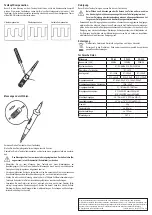
Contact probe compensation
Before making a measurement with the contact probe, check the compensation. Most oscil-
loscopes have a rectangle generator with a 1 KHz testing signal for this purpose. If the com-
pensation is necessary, it can be re-adjusted with the enclosed trim pin on the BNC connector.
Under-compensation
Over-compensation
Correct compensation
Making measurements
Connect the contact probe with the oscilloscope.
Set the attenuation switch to the correct position.
Check the contact probe compensation and adjust it according to the instructions.
The measuring signal should only be applied to the internal conductor. The
external conductor (reference earth) is connected to the earth potential (pro-
tective earth conductor)
• Check the contact probe and its measuring leads for any damage before each measurement.
Never take any measurements if the protecting insulation is defective (torn, missing, etc.).
• To avoid electric shock, do not touch the connections/measuring points directly or indirectly
during measurements.
• Never reach beyond the grip surface of the probes during a measurement process. There is
danger of a life-threatening electric shock.
• Do not use the device shortly before or after a thunderstorm (lightning! / high-power surges!).
Make sure that your hands, shoes, clothing, the floor, the measuring device and/or measuring
lines, circuits and circuit components are always dry.
Cleaning
Before cleaning the device, disconnect it from the oscilloscope.
Live components may be exposed if the covers are opened or parts are re-
moved, unless this can be done manually without tools.
Prior to cleaning or repairing the device, all lines must be detached and the
device must be turned off.
• Do not use scouring, chemical or aggressive cleaning agents such as benzene, alcohol or
such like. These might attack the surface of the device. Furthermore, the fumes are explosive
and hazardous to your health. Moreover, you should not use sharp-edged tools, screwdrivers
or metal brushes or the like for cleaning
• For cleaning the device or the display and the measuring cables, use a clean, slightly damp,
fuzz-free, antistatic cloth.
Disposal
Electronic devices are recyclable material and do not belong in the household waste.
Dispose of an unserviceable product in accordance with the relevant statutory regu-
lations.
Technical data
General information
PP-80
PP-100
PP-200
Bandwidth (-3dB)
80MHz
100MHz
200MHz
System band width
X1: DC-6MHz X10: DC- 200MHz
Attenuation
X1 / X10
Rise time
X1: <50nS
X1: <50nS
X1: <50nS
X10: <4,3nS
X10: <3,5nS
X10: <1,75nS
Input capacity
X1: 85pF-115pF X10: 18,5pF-22,5pF
Oscilloscope input capacity
15pF - 40pF
Input resistance
X1: 1M Ohm X2: 10M Ohm
Max. input current
X1: <200V/DC or <200Vp/AC
X10: <600V/DC or <600Vp/AC
Working conditions
-10 °C to +50 °C (15% to 80% rF)
Storage conditions
-20 °C to +75°C (15% to 85% rF)
Weight
55 g
Size of contact probe
approx. 95 mm
Coaxial cable length
approx. 120 cm
Measuring category
CAT II


