2,19 if to assume it is that a safe operation is no longer possible, then is the device out of operation to set and
against unintentional operation protect. It is to be assumed that a safe operation is no longer possible, if - the
device or the mains cable visible damages indicates, - the device any longer does not operate, - after longer
storage under unfavorable conditions, - after heavy transport stresses.
3. getting started
a) Connection
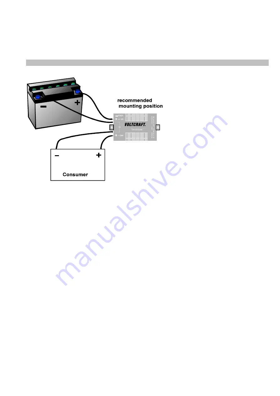
Connect battery and consumer like in the figure. (you pay attention at transducer receipt of+/ battery -- at
transducer receipt/cat transducer / consumer to the polarity of battery and consumer at this -- at
transducer egress-). We don't assume any skid resistance arise from wrong connection this one for damages! Think
highly of you also on a sufficient cross-cut of the supply (for mind. 2.5 mm ²) The transducer doesn't have any one
for-/ shutdown
.
The spacing current of the transducer without connected consumer is approx. 30 mA. Therefore we
recommend the mounting of a switch at solid mounting.
B) safeguarding change
The wiring is interpreted so that a faulty construction element is generally the reason for this in the transducer that
the safeguarding blows. You can check the state of the safeguarding at the inferred equipment. Look to this by the
ventilation slits besides the safeguarding symbol on the Case. For changing the safeguarding you must open the
case. Separate the equipment to this from the battery and from the consumer. Solve the screws of the Case.
Remove the old safeguarding and replace these by a 25 ares FKS safeguarding (flat safeguarding use).
Caution! Burning danger!
The equipment waiter you pay attention therefore absolutely to a sufficient ventilation of the equipment and never conceal they
the ventilation slots on -- or equipment underside, avoid around possible damages. Take care at the connection of a consumer
absolutely that this is connected in the state not switched on.
Attention!
Follow the safety notes absolutely under section 2 of this instruction.


