


Modular IoT Gateway User Guide
V1R1
www.volansys.com
I Email:
Copyright
©
2017 VOLANSYS
Page |
16
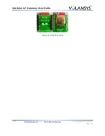
Figure 10 - Modular Gateway Back Side
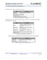
Different control mechanism for switch is provided as below:
Switch
Control
Last State
Next State
SW1
Short Press
( >5sec &
< 15sec)
NFC Commission Window Off
Start NFC commission window
NFC Commission Window ON
Stop NFC commission window
Long press
(> 15sec)
Any
Power off gateway board
Table 7 - User Interface Switch
3.9.2
Reset Switch
One reset switch is provided for user, to reboot the system without removing power supply. Pressing
the switch will drive logic zero on RESETn signal, which will affects every modules on gateway.
3.10
User LED Indications
Two dual color LEDs are used to provide indication about different Gateway functionalities. Below table
indicates color mark to represent specific events.
LED
Behavior
Represents
LED1
Green
Connected to cloud
Red
Not Connected to cloud
Orange
Connecting to cloud
LED2
Green
Commission window is On
Orange
Commission window is Off
Blink fast for 10 times
ED Commission successful
Blink slow for 5 times
ED Commission failed
Table 8 - User LED Indications
Note: User can change LEDs behavior based on their use case scenario.


