


Modular IoT Gateway User Guide
V1R1
www.volansys.com
I Email:
Copyright
©
2017 VOLANSYS
Page |
15
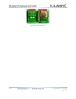
Provides SDIO interface for Wi-Fi and UART interface for Bluetooth operation
External u.fl connectors is connected with antenna line of module to provide external Whip
antenna support
3.7
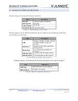
USB Debug Connector (J20)
Modular Gateway comes with one microUSB debug port support to simplify debugging mechanism.
A CP2102, USB to serial UART IC is used to convert the UART signals to USB. A micro-B to standard A USB
cable can be used. UART1 port is used as the debug port.
The required terminal settings are shown in the following table:
Baud Rate
115200
Data Bits
8
Parity
None
Stop Bits
1
Flow Control
None
Table 6 - Terminal Settings
3.8
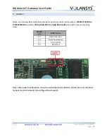
JTAG Connector (J21)
J21 has been used as JTAG connector, it’s a 10 pin header. User will require to have 10 to 20-pin
convertor to use standard JTAG debugger.
Pin out of JTAG header are shown in below figure.
Figure 9 - JTAG Pin Definition
3.9
User Interface Switch
3.9.1
Commissioning Switch (SW1)
SW1 is used to start/stop NFC commissioning mode. It is also used to power off the gateway board by
long pressing it for more than 15 sec.


