Incubus System User Guide V1.1
Page 31
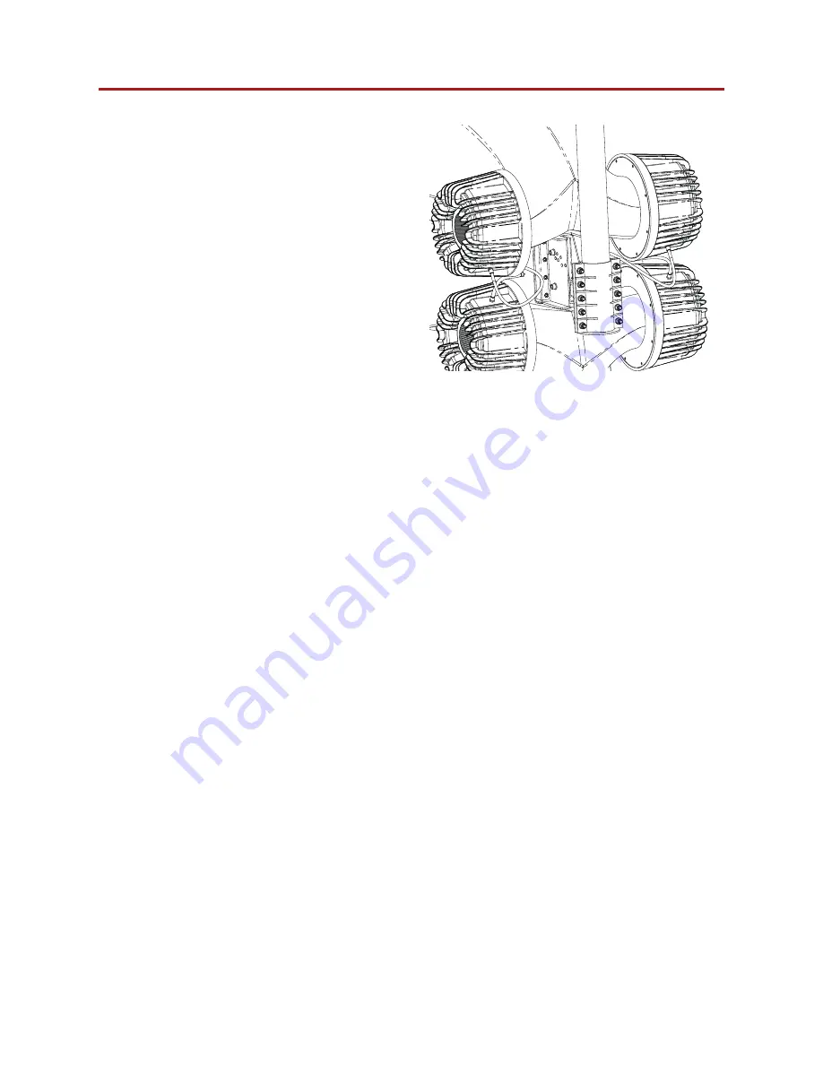
8.3 Flying bracket
Step 6:
Fit the M12 through the appropriate slot.
Figure 8.11: M12 bolt fixing
Page 1: ...Incubus System User Guide V1 1...
Page 2: ...without notice For the latest online version visit www voidacoustics com Void Acoustics and the Void logo are registered trademarks of Void Acoustics Research Ltd in the United Kingdom USA and other c...
Page 3: ...b speci cations 12 5 3 3 Incubus Sub dimensions 13 5 3 4 Incubus Sub impedance graph 13 6 Cabling and wiring 14 6 1 Electrical safety 14 6 2 Cable consideration for xed installations 14 6 3 Typical am...
Page 4: ...less exposure needed to cause such damage Avoid prolonged exposure to the high sound levels from the loudspeaker 1 2 Limitations This guide is provided to help familiarise the user with the loudspeak...
Page 5: ...ntre will initiate corrective repairs upon receipt of the returned product Please save the original carton and all the packing materials in case shipping is required All products being returned to the...
Page 6: ...of its contents are found to be damaged inform the shipping company and inform your dealer Air Array loudspeakers are heavy 144 8 kg 319 lbs including stand and require a minimum two people to lift Un...
Page 7: ...rings you years of satisfaction This guide will help you both use this product safely and ensure it performs to its full capability 4 2 Incubus series overview Designed with the sole purpose of being...
Page 8: ...dB 1W 1m HF 116 dB 1W 1m Crossover point Preset via dedicated processor Nominal impedance LF 2 x 4 MF 2 x 4 HF 2 x 5 33 Power handling2 LF 3600 W AES MF 800 W AES HF 320 W AES Maximum output3 143 dB...
Page 9: ...System User Guide V1 1 Page 9 5 1 3 Air Array dimensions 944 37 2 1422 56 944 37 2 1012 39 8 944 37 2 1012 39 8 813 32 1012 39 8 944 37 2 1422 56 1240 48 8 Figure 5 1 Dimensions 5 Speci cations and di...
Page 10: ...sponse 60 Hz 190 Hz 3 dB Efficiency1 109 5 dB 1W 1m Crossover points Preset via dedicated processor Nominal impedance 2 x 4 Power handling2 4000 W AES Maximum output3 142 dB cont 145 dB peak Con gurat...
Page 11: ...1 1218 47 9 738 29 1 738 29 1 738 29 1 1218 47 9 748 29 4 738 29 1 748 29 4 1218 47 9 Figure 5 2 Dimensions 5 Speci cations and dimensions 5 2 4 Hyperfold impedance graph 10 100 20 50 200 500 1k 2k 5k...
Page 12: ...z 95 Hz 3 dB Efficiency1 105 dB 1W 1m Crossover point Preset via dedicated processor Nominal impedance 3 x 8 Power Handling2 6000 W AES Maximum output3 140 dB cont 146 dB peak Driver con guration 3 x...
Page 13: ...48 1479 58 2 1479 58 2 1218 696 27 4 1218 48 704 27 7 1479 58 2 704 27 7 1225 48 2 1225 48 2 Figure 5 4 Dimensions 5 Speci cations and dimensions 5 3 4 Incubus Sub impedance graph 10 100 20 50 200 500...
Page 14: ...0 or above Cables for permanent installations should be compliant with the following standards IEC 60332 1 Fire retardancy of a single cable IEC 60332 3C Fire retardancy of bunched cables IEC 60754 1...
Page 15: ...the rear of the Air Array will be referred to speakONTM A for the left and speakONTM B for the right as shown in gure 6 1 A further aid given will be a diagrammatic representation of which drivers wou...
Page 16: ...1 1 2 2 3 3 4 4 Right 1 1 2 2 3 3 4 4 Bottom 3 MF speakONTM A NL8 Pins Driver Power handling Impedance 1 Bottom 2 x 12 1800 W AES 4 2 Top 2 x 12 1800 W AES 4 speakONTM B NL8 Pins Driver Power handling...
Page 17: ...Bias Q5 speakONTM A wiring LF 1 LF 1 LF 1 LF 2 LF 2 LF 1 LF 2 LF 2 Figure 6 6 Bias V3 left speakONTM A connection NOTE pins 3 and 4 are not connected Bias Q5 for LF speakONTM A connection Channel Chan...
Page 18: ...F 2 HF 4 HF 2 HF 4 Figure 6 7 Bias Q5 right speakONTM connection Bias Q5 for HF speakONTM B connection Output 2 Channel 3 Channel 4 Output Bottom 3 x 1 HF Top 3 x 1 HF speakONTM NL8 pins 3 4 6 7 Air A...
Page 19: ...LF 6 8 Hyperfold wiring diagram speakONTM pins 1 speakONTM pins 2 In LF 2 x 15 LF 2 x 15 Out LF link LF link Figure 6 8 Wiring diagram 6 9 Hyperfold Bias Q5 speakONTM wiring 1 1 2 2 1 1 2 2 Figure 6 9...
Page 20: ...wiring 1 1 2 2 3 3 4 4 In 1 1 2 2 3 3 4 4 21 LF 2 21 LF 1 21 LF 3 1 1 2 2 3 3 4 4 Out Link 1 1 2 2 3 3 4 4 6 10 Incubus Sub wiring diagram Figure 6 10 Wiring diagram speakONTM pins 1 2 3 4 In 21 LF 1...
Page 21: ...LF 3 LF 3 Incubus Sub 1 Incubus Sub 2 In Out Link In Out Link LF 1 LF 1 LF 2 LF 2 LF 3 LF 3 LF 1 LF 1 LF 2 LF 2 LF 3 LF 3 Figure 6 11 Bias Q5 Ampli er Bias Q5 1 Bias Q5 2 Output Output 1 Output 2 Outp...
Page 22: ...g forward to provide a wide stereo image For permanent installation it is recommended to y the Air Array loudspeakers for more even coverage This also allows co located low frequency enclosures in a s...
Page 23: ...require more ll loudspeakers than are necessary to achieve required coverage Following are some basic guidelines when considering the vertical position of your Air Array loudspeaker With optimum vert...
Page 24: ...taken to counter unwanted room effects Careful positioning and aiming of loudspeakers will minimise room effects while maintaining even coverage throughout the audience area Figure 7 5 Multi point lo...
Page 25: ...hot dance oor leading to reduced HF penetration at mid and far distances again reducing intelligibility and coherence In gure 7 8 the loudspeakers vertical positioning is too low for the audience are...
Page 26: ...ulations This may include consulting a structural engineer before installation of wall brackets Remember that all personnel have a duty of care to themselves to their assistants to the venue staff and...
Page 27: ...emoving both M12 bolts from the bracket assembly Figure 8 1 Backing plate removal Step 2 Remove all eight M8 bolts from the rear of the Air Array loudspeaker Figure 8 2 M8 bolt removal Step 3 Attached...
Page 28: ...akers are heavy and require a minimum of two people to lift At this stage of the mounting procedure it becomes necessary to have three people two to lift the Air Array loudspeaker and one to attach th...
Page 29: ...ng both M12 bolts from the bracket assembly Figure 8 6 Backing plate removal Step 2 Remove all eight M8 bolts from the rear of the Air Array loudspeaker Figure 8 7 M8 bolt removal Note Flying the Air...
Page 30: ...on onto the bracket assembly and attach the M12 bolt through the bracket assembly Note Air Array loudspeakers are heavy and require a minimum of two people to lift At this stage of the mounting proced...
Page 31: ...Incubus System User Guide V1 1 Page 31 8 3 Flying bracket Step 6 Fit the M12 through the appropriate slot Figure 8 11 M12 bolt xing...
Page 32: ...aking adjustments please note the following Removing the grille can cause debris to collect within the enclosure take care to remove anything that may have collected internally Do not use impact tools...
Page 33: ...sing a 4 mm Allen key take care NOT to remove the tab bolts as they may become lost within the enclosure Figure 9 5 Grille removal Step 2 Remove grille Step 3 Replace the M6 bolts by hand until nger t...
Page 34: ...our dealer will need to see a copy of your sales receipt as proof of purchase so please have this to hand when applying for return authorisation 10 2 Shipping and packing considerations When sending a...
Page 35: ...um magnets for high power handling and long term reliability Each 3 MF transducer shall have a 6 diaphragm reproducing frequencies down to 500 Hz and shall be mounted on a high standard waveguide with...
Page 36: ...e 60 Hz to 190 Hz 3 dB maximum SPL of 145 dB peak 142 dB continuous measured at 1 m using IEC268 5 pink noise Power handling shall be 4000 W AES at a rated impedance of 2 2 x 4 with pressure sensitivi...
Page 37: ...h of 29 Hz to 95 Hz 3 dB with a maximum SPL of 146 dB peak 140 dB continuous measured at 1 m using IEC268 5 pink noise Power handling shall be 6000 W AES at a rated impedance of 3 x 8 and a pressure s...
Page 38: ......
Page 39: ......
Page 40: ...Research Ltd Unit 15 Dawkins Road Industrial Estate Poole Dorset BH15 4JY England 44 0 1202 666 006 info voidacoustics com Registered in England Wales No 07533536 North America Void Acoustics North A...