Asse mbl y
32
WBV.PU.002.EN VX186QD V2.0
6.6
Drive
The technical
specifications for the drive system to be installed are determined by the machine’s
specifications
Chap.
"Specifications".
In addition, also read and observe the following:
"Technical information for the drive system to be installed"
"System requirements - Electrical drive technology"
WARNING
Injuries caused by friction, catching, grazing from the exposed rotating drive shaft/coupling!
If the machine starts up unexpectedly during assembly or repair work, this can result in accidental contact
with the exposed rotating drive shaft/coupling.
•
The coupling area must be protected by a screwed cover.
•
The machine may only be started up again after maintenance, repairs or trouble-shooting once all the
protective equipment has been re-installed.
•
Before starting assembly and repair work on the coupling, switch the machine off and secure it against
being switched on again.
6.6.1
Electric drive
Connection to the energy supply may only be established by qualified technical personnel
following
installation in the pipe.
RISK OF ELECTRIC SHOCK
Touching live parts leads to dangerous electrocution.
This can result in electric shock, burns or death.
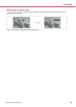
RISK OF ELECTRIC SHOCK
The equipotential bonding shall be executed in accordance with standard EN 60204-1. In other words, all
metallic parts of the machine or plant must be connected electroconductively to each other or to the signal
ground.
@ 39\ mod_1259315210400_6. doc @ 141472 @
In addition, also read and note the following:
"Technical information for geared motor"
Before connecting the geared motor (electric motor with or without gearbox)
•
Check that the power supply is correct for the motor.
•
Check that the power feed and fuse protection are adequately dimensioned to allow for multiple
rotation direction changes and peak loads within a short period of time.
•
Be sure to follow the cable layout diagram on the inside of the motor terminal box cover.
•
Note that the PTC resistor of the geared motor must be connected to the terminals provided on the
pump control, to a PTC control unit or to a variable frequency drive with a PTC input (each available
as an option).
•
Install a maintenance switch in close proximity to the machine (recommendation).

