


ACHTUNG:
Bei der Montage von Heizkörpern ist zu beachten, dass die
Befestigung von Heizkörpern so dimensioniert wird, dass sie für die bestim-
mungsgemäße Verwendung und vorhersehbarer Fehlanwendung geeignet ist.
Hierbei sind insbesondere die Verbindung mit dem Baukörper sowie dessen
Beschaffenheit, die Geeignetheit des Montagezubehöres und die möglichen
Belastungen nach erfolgter Montage zu prüfen.
BEI VHV MIT AUFGESCHWEISSTEN LASCHEN:
•
Schnellmontagekonsole ab BH 358 für VHV 11.
•
Auf Sonderwunsch ist der VHV 11 ab BH 214 bzw. der VHV 23 ab BH 214 bis
BH 286 mit aufgeschweißten Laschen verfügbar. (Wandmontage somit auch
mit der Schnellmontagekonsole ab BH 214 möglich).
•
Die entsprechenden Montageanleitungen sind den jeweils verwendeten
Befestigungssets zu entnehmen.
BEI VHV OHNE LASCHEN:
•
Stand- bzw. Wandkonsolen können für alle VHV bis BH 286 verwendet werden.
•
Verwendung der Standkonsole
SK 22
für VHV 20, ab BH 358 bis BH 574 bzw.
SK 23
für VHV 11 und VHV 22, ab BH 358 bis BH 646.
BEI VHV MIT EINSCHIEBELASCHEN:
•
Schnellmontagekonsole ab BH 214 - 790 für Type VHV 20 und Type VHV 22
bzw. ab BH 214 - 286 für Type VHV 34.
•
Die entsprechenden Montageanleitungen sind den jeweilig verwendeten
Befestigungssets zu entnehmen.
BEI VERWENDUNG DER SCHNELLMONTAGEKONSOLE:
•
An den Stirnflächen der Schutzecken die Schrumpffolie öffnen.
•
Schutzecken entfernen und den darunterliegenden Karton mittels Tapezier-
messer vorsichtig im Bereich der Aufhängelaschen aufschneiden.
•
Ab BL 2200 ist ein drittes Laschenpaar (Baulängenmitte) vorhanden. Das in
der Mitte liegende Aufhängelaschenpaar vorsichtig mit dem Tapeziermesser
freistellen.
•
Befestigung der Wandschiene laut Laschenaufschweißbild.
•
VHV-Montage nach Montageanleitung der Schnellmontagekonsole.
BEI VERWENDUNG DER SCHNELLMONTAGEKONSOLE:
•
Freistellung des Führungsspaltes für die Einschiebelasche durch Auf-
schneiden der Schrumpffolie, der Schutzecken und des Kartons in
Längsrichtung der VHV, in vorgegebenem Abstand.
•
Ab BL 2200 ist eine zusätzliche Fußkonsole in Baulängenmitte der VHV zu
montieren.
•
VHV-Montage nach Montageanleitung der Schnellmontagekonsole.
Achtung: Eine Montage der VHV mit Einschiebelasche ist nur in
Kombination mit der Schnellmontagekonsole erlaubt!
1.) BEI VERWENDUNG DER STAND- UND/ODER WANDKONSOLE
(SK 10 - 19 BZW. WK 10 - 12):
•
Schrumpffolie an der Unterseite der VHV öffnen.
•
Schutzecken entfernen, und den Karton mittels Tapeziermesser vorsichtig,
im durch die Montageanleitung der verwendeten Konsole vorgegebenen
Montagebereich, ausschneiden.
•
Positionierung der Konsolen nach
Skizze A
.
•
Montage der VHV laut Montageanleitung der verwendeten Konsole.
2.) BEI VERWENDUNG DER STANDKONSOLEN SK 22 UND SK 23:
•
Gleiche Vorgehensweise wie in
Punkt 1.
beschrieben.
Diese VHV-S haben einen integrierten Strahlungsschirm, der sich auf der gegen-
überliegenden Seite dieser Montageanleitung befindet. Montage mittels
Standkonsole.
ZU VERWENDENDE AUFHÄNGUNGEN
ATTENTION:
For the correct installation of radiators it is essential that the
fixing of the radiator is carried out in such a way that it is suitable for intended
use AND predictable misuse. A number of elements need to be taken into consi-
deration including the fixing method used to secure the radiator to the wall, the
type and condition of the wall itself, and any additional potential forces or
weights, prior to finalising installation.
VHV WITH WELDED BRACKETS:
•
Quick-fit bracket from OH 358 for VHV 11.
•
VHV 11 from OH 214 of VHV 23 from OH 214 to OH 286 available with welded
brackets against special order (wall mounting therefore possible also with
quick-fit bracket from OH 214).
•
The relevant installation instructions can be found in the fixing kits used.
VHV WITHOUT BRACKETS:
•
Floor brackets or wall brackets may be used for all VHV up to OH 286.
•
Floor brackets
SK 22
may be used for VHV 20 from OH 358 up to OH 574 or
SK 23
for VHV 11, VHV 22 from OH 358 up to OH 646.
VHV WITH SLIDE-IN BRACKETS:
•
Quick-fit brackets from OH 214 to 790 for model VHV 20 and model VHV 22,
from OH 214 to BH 286 for model VHV 34.
•
The relevant installation instructions can be found in the fixing kits used.
WHEN USING QUICK-FIT MOUNTING BRACKET:
•
Open the shrink wrapping on the corner protector front faces.
•
Remove the corner protectors and carefully cut the cardboard behind in the
area of the mounting brackets using a wallpaper knife.
•
From OL 2200, a third pair of brackets is provided (centre of overall length).
Carefully free the central pair of brackets using the wallpaper knife.
•
Fit the wall rail in accordance with the bracket welding diagram. Fit the VHV in
accordance with the quick-fit mounting bracket fitting instructions.
WHEN USING QUICK-FIT MOUNTING BRACKET:
•
Free the slide-in bracket guide slot by cutting the shrink wrapping, corner
protectors and cardboard along the VHV at the distances shown.
•
From OL 2200, an additional floor bracket should be fitted in the centre of the
VHV overall length.
•
Fit the VHV in accordance with the quick-fit bracket fitting instructions.
Important: Installation of VHV with slide in bracket is permissible
only in combination with quick fit mounting-bracket.
1.) WHEN USING FLOOR MOUNTING OR WALL MOUNTING BRACKET (SK
10 - 19 OR WK 10 - 12):
•
Open the shrink wrapping on the underside of the VHV.
•
Remove the corner protectors and, using a wallpaper
knife, carefully cut the cardboard in the fitting area
shown in the fitting instructions for the bracket used.
•
Position the brackets as shown in
diagram A
.
•
Fit the VHV in accordance with the fitting instructions
for the bracket used.
2.) WHEN USING FLOOR BRACKETS SK 22
and SK 23:
•
Proceed as described under
1.)
.
These VHV-S are fitted with an integral radiation reflector on the opposite side of
these fitting instructions. Fit using the standard bracket.
D
MOUNTINGS TO BE USED
GB
MONTAGEHINWEISE FÜR VHV
MIT AUFGESCHWEISSTEN LASCHEN
D
MONTAGEHINWEISE FÜR VHV
MIT EINSCHIEBELASCHEN
D
MONTAGEHINWEISE FÜR
VHV OHNE LASCHEN
D
MONTAGEHINWEISE FÜR VHV-S (BH 142, 214 UND
286)
D
Achtung: Die zulässige Druckstufe (5,0 bzw. 8,0 bar)
und die zulässige Temperatur (110 °C) sind einzuhalten.
HINTS FOR INSTALLATION OF VHV
WITH WELDED BRACKETS
GB
HINTS FOR INSTALLATION OF VHV
WITH SLIDE-IN BRACKETS
GB
HINTS FOR INSTALLATION OF VHV
WITHOUT BRACKETS
GB
HINTS FOR INSTALLATION OF VHV-S
(OH 142, 214 AND 286)
GB
Important: The permissible pressure level (5.0 or 8.0 bar) and the permis-
sible temperature (110 °C) must be adhered to.
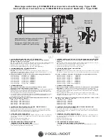
Y
Z
XX
BL/2
BL/2
BH
LASCHENAUFSCHWEISSBILD
BRACKET WELDING DIAGRAM
BH
574
646
790
X
160
160
160
Y
130
130
130
Z
420
420
420
KONSOLENPOSITIONIERUNG (SKIZZE A)
BRACKET POSITIONING (DIAGRAM A)
BH
214
286
358
430
502
X
160
160
160
160
160
Y
85
130
130
130
130
Z
120
120
220
220
220
3. Laschenpaar ab BL 2200 mm
3
rd
pair of brackets from OL 2200 mm
BL/2
BL/2
aa
SK 10 - 23: 3.
Konsole ab
BL 2200 mm
WK 10 - 12:
Konsolenanzahl laut der
Konsole beiligender Montageanleitung.
SK 10 - 23: 3
rd
bracket from
OL 2200 mm
WK 10 - 12:
No. of brackets according to
fitting instructions enclosed with bracket
SK
22
a = 110 mm
SK
23
a = 165 mm
WK
10 - 12
a = 150 mm
SK
10 - 19
a = 150 mm


