


1.) VOR DER MONTAGE DES VHV IST ZU BEACHTEN:
• Das Ventil des VHV ist werkseitig auf Zweirohrbetrieb mit dem
größten kv-Wert voreingestellt.
•
Die Typen VHV 20, VHV 22, VHV 34 und VHV 46 ohne Laschen sind drehbar und
können wahlweise unten rechts oder unten links angeschlossen werden.
•
Entfernen der Verpackung im VHV - Anschlussbereich.
•
Demontage der Abdeckkappen von den 3/4” Außengewinden.
2.) ZWEIROHRBETRIEB - VOREINSTELLUNG:
•
Demontage der Baustellenkappe
1
.
• Detail A:
Einstellring des Ventiles
2
gegen den Uhrzeigersinn auf die
gewünschte Voreinstellung drehen - der gewünschte Einstellwert (1, 2,..7, N)
muß über der Markierung positioniert sein.
kv-Werteinstellungen bei 2K Proportionalabweichung (Richtwerte):
Voreinstellung 1
für VHV bis ca. 500 Watt
Voreinstellung 2
für VHV bis ca. 800 Watt
Voreinstellung 3
für VHV bis ca. 1000 Watt
Voreinstellung 4
für VHV bis ca. 1200 Watt
Voreinstellung 5
für VHV bis ca. 1600 Watt
Voreinstellung 6
für VHV bis ca. 2000 Watt
Voreinstellung 7
für VHV bis ca. 2400 Watt
Voreinstellung N
für VHV über 2400 Watt
3.) EINROHRBETRIEB:
• Eine Ventilvoreinstellung ist nicht notwendig, da das Ventil 2
werkseitig auf Voreinstellung N justiert wurde.
• Achtung:
Um eine unerwünschte Erwärmung des VHV im Einrohrbetrieb bei
geschlossenem Ventil möglichst gering zu halten, ist bei der Montage des
Einrohrverteilers
3
zu beachten, daß der Rücklaufeinsatz
4
im Rücklauf und
der Vorlaufeinsatz
5
im Vorlauf eingebaut sind.
•
Vor der Einstellung des Heizkörperanteiles ist die Abdeckkappe
6
am Einrohr-
verteiler
3
zu entfernen und die darunter befindliche Beipaßspindel nach
rechts bis zum Anschlag einzudrehen.
Einstellwerte bei 2K Proportionalabweichung (Richtwerte bei TV = 70
°C, TR = 55 °C und TL = 20 °C):
HK-Anteil 30% - 3,50 Umdrehungen
HK-Anteil 35% - 3,00 Umdrehungen
HK-Anteil 40% - 2,50 Umdrehungen
HK-Anteil 45% - 2,00 Umdrehungen
HK-Anteil 50% - 1,75 Umdrehungen
4.) MONTAGE UND ANSCHLUSS VON VOR- UND RÜCKLAUF:
•
VHV montieren (siehe Montagehinweise).
•
Bei Einrohrsystemen Einrohrverteiler
3
montieren, Vorlauf- und Rücklauf-
leitung mit Klemmverschraubungen
7
anschließen. Bei Zweirohrsystemen
sollten Absperrverschraubungen
8
eingebaut werden.
5.) THERMOSTATKOPFMONTAGE:
Die Thermostatköpfe ”RA 2000” und ”RAW” Fa. Danfoss, ”VK” Fa. Heimeier,
”D” Fa. Herz, ”thera-DA” Fa. MNG und ”UNI-LD” Fa. Oventrop sind direkt
montierbar.
•
Demontage der Baustellenkappe
1
.
•
Montage des Thermostatkopfes
9
.
6.) ÄNDERUNGEN DER EINSTELLWERTE IM
ZWEIROHR- UND EINROHRBETRIEB:
Bei Bedarf können die entsprechenden Einstellwerte
auch unter Anlagendruck verstellt werden.
1.) BEFORE INSTALLING THE VHV, THE FOLLOWING SHOULD BE NOTED:
• The VHV valve is factory set for two-pipe operation with the largest
kv-value.
•
VHV 20, VHV 22, VHV 34 and VHV 46 models without brackets can be rotated
and optionally connected at bottom right or bottom left.
•
Remove packaging around the VHV connection area.
•
Remove protective cap 1 from 3/4” male threads.
2.) TWO-PIPE OPERATION - PRE-SETTING:
•
Remove protective cap
1
.
• Detail A:
Turn the adjustment ring of valve
2
counter clockwise to the required
pre-setting - the pre-set value (1, 2,..7, N) should be positioned over the marking.
kv-value settings at 2K proportional deviation (approximate values):
default setting 1
for VHV to
500 Watt
default setting 2
for VHV to
800 Watt
default setting 3
for VHV to
1000 Watt
default setting 4
for VHV to
1200 Watt
default setting 5
for VHV to
1600 Watt
default setting 6
for VHV to
2000 Watt
default setting 7
for VHV to
2400 Watt
default setting N
for VHV above 2400 Watt
3.) SINGLE-PIPE OPERATION:
• No valve pre-setting required, as valve 2 is factory set to pre-setting N.
• Important:
To minimise undesirable warming of the VHV in single-pipe
operation with closed valve, ensure that when fitting the single-pipe manifold
3
the return flow cartridge
4
is installed in the return and the flow cartridge
5
is installed in the flow.
•
Before setting the radiator part, the protective cap
6
on the single-pipe
manifold
3
should be removed and the bypass spindle below screwed in fully
clockwise against the stop.
Setting values at 2K proportional deviation (approximate values at TV =
70 °C, TR = 55 °C and TL = 20 °C):
Radiator part 30% - 3.50 turns
Radiator part 35% - 3.00 turns
Radiator part 40% - 2.50 turns
Radiator part 45% - 2.00 turns
Radiator part 50% - 1.75 turns
4.) INSTALLATION AND CONNECTION OF FLOW AND RETURN:
•
Fit the VHV (see hints for installation).
•
For single-pipe systems install single-pipe manifold
3
and connect flow and
return using compression fittings
7
. For two-pipe systems shut-off fittings
8
should be used.
5.) THERMOSTAT HEAD INSTALLATION:
The thermostat heads ”RA 2000” and ”RAW” by Danfoss, ”VK” by Heimeier,
”D” by Herz, ”thera-DA”by MNG and ”UNI-LD” BY Oventrop are suitable for
direct installation.
•
Remove the protective cap
1
.
•
Install the thermostat head
9
.
6.) ADJUSTMENT OF SETTING VALUES
IN TWO-PIPE AND SINGLE-PIPE OPERATION:
If required, the relevant setting values may also be adjusted under system
pressure.
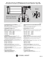
50
25
2
N
1
A
Vorlauf
Flow
Départ
Rücklauf
Return
Retour
4
3
7
8
7
7
6
9
5
N
1234
567
Einstellring
Adjustment ring
Bague de réglage
Markierung
Marking
Index
M o n t a g e a n l e i t u n g V O N A R I S H o r i z o n t a l e A u s f ü h r u n g Ty p e V H V
I n s t a l l a t i o n I n s t r u c t i o n s V O N A R I S H o r i z o n t a l R a d i a t o r Ty p e V H V
D
GB
KMBA04
Detail A
Detail A
Abgebildete Darstellung: rechter Anschluss
Linker Anschluss: spiegelverkehrt
Illustration: Right hand connection
Left hand connection: mirror image
VOGEL
&
NOOT
Vorlauf
Flow
Rücklauf
Return
Einstellring
Adjustment ring
Markierung
Marking


