background image

9

Getting started cont.

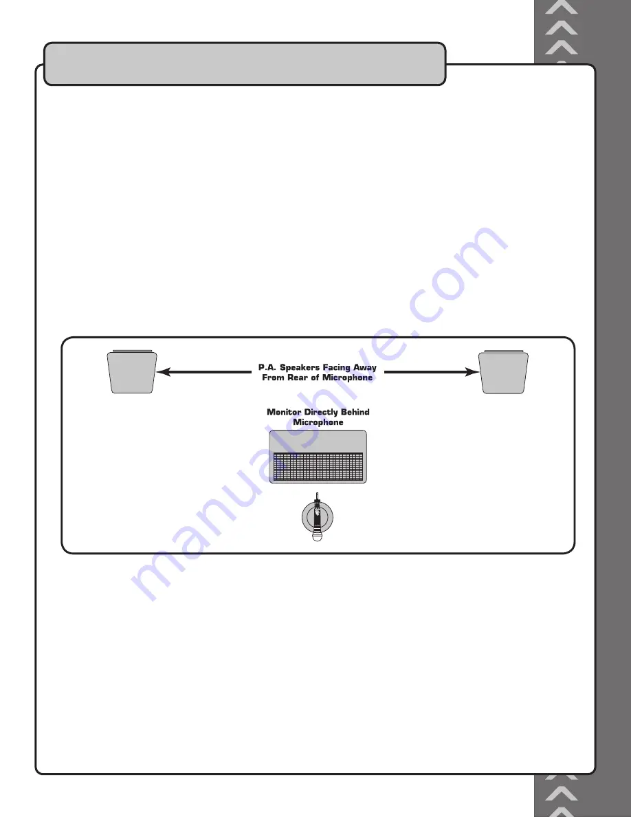
Setting Up on Stage

If you will be using the UHF-6800 with stage monitors and/or a P.A. system, try the following:

• Place the stage monitor directly behind the microphone.

• Locate the P.A. loudspeakers so that they point away from the rear of the microphone. (With the speakers located

in these positions, the possibility of feedback is greatly reduced).

• Always check the stage setup before a performance to ensure optimum placement of microphone and monitors.

IMPORTANT: Every wireless microphone installation is a unique situation, and can present a variety of problems.

Never attempt a live performance without first conducting a “walkthrough” test of the system in the performing area.

If major changes (additional wireless systems or intercoms, relocation of scenery, etc.) have been made since the last

walk-through test, check the wireless system again, as close to performance time as possible.

Summary of Contents for UHF-6800

Page 1: ...o w n e r s m a n u a l THE SINGER S ULTIMATE CHOICE UHF 6800 o w n e r s m a n u a l UHF 6800 UHF PLL 100 Frequency Dual Channel Wireless Microphone System...

Page 2: ...necting to a mixer 10 Connecting to an all in one system 10 Controls and Functions Front panel 11 Rear panel 12 Microphone 13 Microphone Basics Microphone position 14 Feedback 14 Microphone placement...

Page 3: ...2...

Page 4: ...3 110V...

Page 5: ...Court La Verne CA 91750 Toll Free 800 678 5348 TEL 909 593 8893 FAX 909 593 8890 VocoPro Company Email Directory Customer Service General Information info vocopro com Tech Support techsupport vocopro...

Page 6: ...5...

Page 7: ...nd requires just 1 RU Speci cations Frequency range 620 950MHz Band range 25MHz Frequency stability 0 005 Active range 110dB Peak frequency 45KHz Frequency response 60Hz 18KHz 3dB Noise ratio 105dB De...

Page 8: ...ace What you will need 19 Rack case not included 4 Mounting screws not included 1 RU of available rack space Phillips head screwdriver not included To mount 1 Carefully line up the holes on the UHF 68...

Page 9: ...nect the output end to the AC Power input on the rear panel of the UHF 6800 2 Connect the AC adapter to a power outlet NOTE It is recommended that you connect to a power strip surge protector for adde...

Page 10: ...s greatly reduced Always check the stage setup before a performance to ensure optimum placement of microphone and monitors IMPORTANT Every wireless microphone installation is a unique situation and ca...

Page 11: ...integrate the UHF 6800 into your audio system Mixer All In One System Connecting to a Mixer Connect each mic channel to separate channels on the mixer using the BALANCED XLR outputs Fig A or output bo...

Page 12: ...selection when navigating through the Frequency Channel select menu on the receiver 4 Volume controls Controls the volume for each mic channel Turn clockwise to raise volume and counter clockwise to l...

Page 13: ...is to adjust the squelch to limit unwanted interference See the Adjusting the Squelch section of this manual for instructions on when and how to adjust the squelch level 3 Balanced A and B outputs Out...

Page 14: ...f Slide up to turn the mic on and slide down to turn the mic off 6 Battery compartment Removable lid hides and protects the microphone battery 7 RF Power HI LOW switch Allows you to set the RF power l...

Page 15: ...ak louder into the microphone Reduce the distance from the talker to the microphone Each time this distance is halved the sound system output will increase by 6dB Reduce the number of open microphones...

Page 16: ...unit is on To power off 1 Hold down the POWER button for 2 seconds Turning On Off the UHF 6800 Mic Slide the power switch to the ON position to turn the mic on and slide it to the OFF position to turn...

Page 17: ...e microphone to select the desired frequency 3 The number will stop blinking and the frequency will be set Changing the Display The UHF 6800 gives you the option of viewing the actual frequency number...

Page 18: ...B 2 The LCD screen for the chosen mic channel will begin blinking 3 Press the SET button twice 4 The word LOCK will quickly ash 5 Press the UP arrow button to turn the lock ON or press the DOWN arrow...

Page 19: ...wer level There are two possible settings for the RF Power High and Low The RF Power level switch is located inside the battery compartment of each microphone To set the RF Power level 1 Open the batt...

Page 20: ...e RF Power Level to HIGH he RF Power Level switch is located inside the battery compartment of each microphone See the instuctions for Setting the RF Power Level in this manual There is noise coming f...

Page 21: ...C THE SINGER S ULTIMATE CHOICE TM R VOCOPRO 2006 Version 1 0 www vocopro com...

Reviews: