


G-405 Quick User Manual Document: G-40501
------------------------------------------------------------------------------------------------------------------------------------------------
25
8 System control
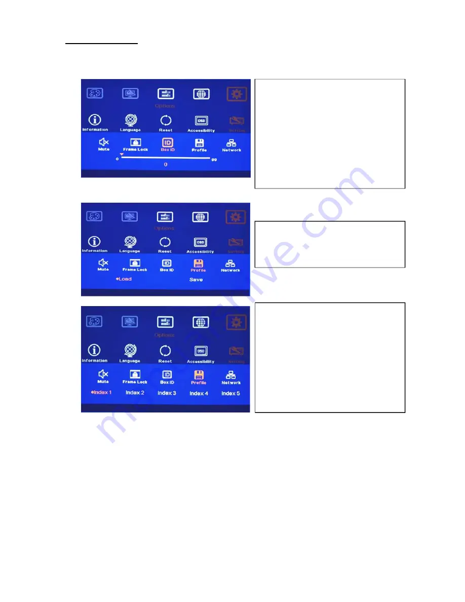
8.1 [Box ID]
8.2 [Profile] Setting
Application example: when cascade with two G-405, user can set four display styles:
1. To show single content across entire video wall.
2. To show two contents across entire video wall.
3. To show 1+3 contents in cascaded image.
4. To show four independent content in each LCD.
User can save these different display styles in G-405 and recall them by RS232 or remote controller.
Please note:
When execute system reset or update the Firmware, Profile settings will remain the same without change.
[Box ID] is identification # in each G-405
module for individual RS232 or IR remote
control.
GeoBox ID No is from 1-99
After set Box ID, user can control GeoBox
individually via IR Remote controller,
RS232 & Ethernet
IR control ID # is from 0-9 only.
[Profile] is to save and load G-405 system
settings.
Five custom Indexes can be saved in
[Profile] and users can recall it through
RS232 and hotkey on front panel or
remote controller.
User can recall Profile setting by [Profile]
hotkey on remote controller following by
number keys to select [Index] for the
display.


