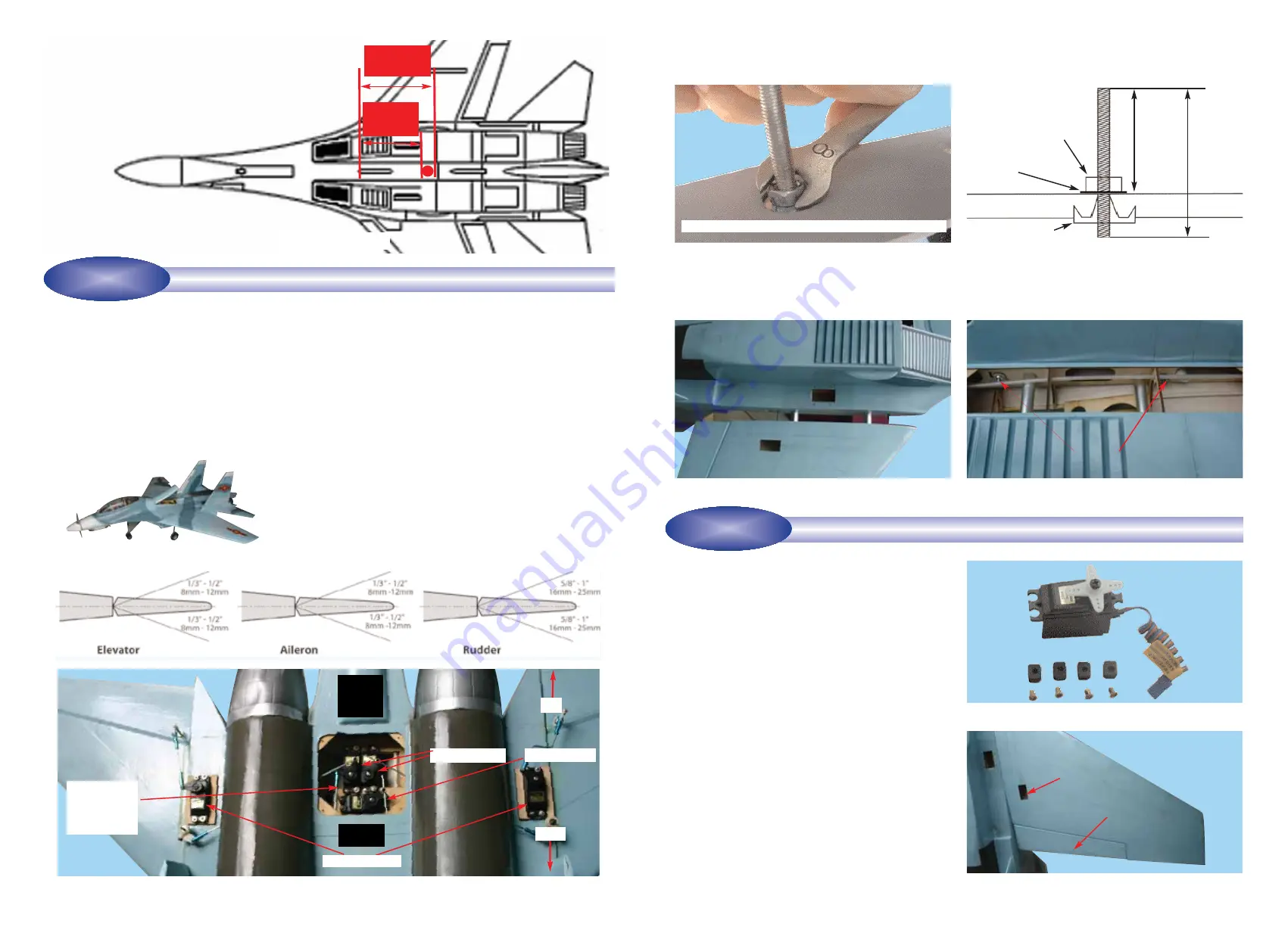
2B - Aileron servo location
3
Step 1.8
While holding the aluminum tubes centered in the
fuselage, carefully slide each wing half onto the tubes and
flush the wing root against the side of the fuselage. See 1J
Step 1.9
Place flat washers over the wing bolts and then
install the butterfly nuts. Do NOT overtighten. For double
security also install the lock nuts. See 1K
1H - Hold the wing bolt while tightening the lock nut
1J - Plug the wing panels into the fuselage
1K - Tighten the wing nuts. DO NOT OVERTIGHTEN. For
double security also install the lock nuts
1I - Typical installation of wing bolts into the wing
Step 1.7
Secure the wing bolt to the wing by tightening the
lock nut. See 1H
Illustration 1I:
Typical installation of the wing bolts into the
pre-installed blind nuts located inside the wing so that 3 in.
(75 mm) of each wing bolt protrudes from the wing root.
4 mm nut
Washer
3-3/4 in.
(95 mm)
4-3/4 in.
(120 mm)
Wing root
Wing nut
4 mm blind nut
Aileron servo cavity
2A - Prepare the servos by fitting the rubber grommets &
ferrules supplied with your servos
To install the aileron servos into the wing you will need the
following items:
- Servos
- Servo mounting screws and grommets as supplied with
servos
- Servo control arms as supplied with servos
- Two aileron control rod assemblies supplied with the kit
The assemblies consist of a metal rod with a clevis on
each end
- Low tack masking tape
- 2 aileron control horn assemblies
Step 2.1
Turn the wings upside down and locate the aileron
servo cavities. See 2B
Step 2.2
Trial fit the aileron servo into the servo mounting
cavity. You may have to modify the cavity slightly to provide
clearance for the servo and servo wires. Use a hobby knife
to modify the cavity as required. Most servos have their out-
put shaft closer to one end than the other. We recommend
locating the servo so that the output shaft is as close to the
rear of the wing as possible.
Aileron
INSTALLING THE AILERON SERVOS INTO THE WING
STAGE 2
14
CONTROL SURFACE THROW SPECIFICATIONS
:
The throws are measured at the widest part of the control
surface. Adjust the position of the pushrods at the control
and/or servo horns to control the amount of throw. You may
also use ATV's if your radio has them but the mechanical
linkages should still be set so that the ATV's are near 100%
for best servo resolution.
Low rate
High rate
ELEVATOR
1/3 in (8mm)
up
1/2 in (12 mm)
up
1/3 in (8mm)
down
1/2 in (12 mm)
down
AILERON
1/3 in (8 mm) up
1/2 in (12 mm)
up
1/3 in (8 mm) down
1/2 in (12 mm)
down
RUDDER
5/8 in (16 mm) right
1 in (25 mm)
right
5/8 in (16 mm) left
1 in (25 mm)
left
CAUTION: Tighten snugly but DO NOT OVERTIGHTEN
CONFIRM MECHANICAL INTEGRITY
STAGE 27
5-1/8 in
(130mm)
4-1/2 in
(120mm)
27A - TYPICAL ARRANGEMENT OF RECEIVER, RECEIVER BATTERY, SERVOS AND PUSH RODS
Rudder servos
Receiver
battery
Nose steering
push rod con-
nected to the
rudder servo
Throttle servo
Receiver
Elevator servos
26A - CG location
Tail
Nose
Step 27.1
Once you have confirmed that the CG is correct, you should do a thorough review of the entire model before
your first flight. Check everything twice! Every hook up, every coupling, everything! Do it twice!!
Step 27.2
Before your first flight, have an experienced flyer review your work. Do not fly your model until it has been
checked out by a third party who knows how to fly and how to set up a model aircraft. Do not fly alone. Seek experi-
enced help.
Step 27.3
Once you have completed your first flight, get in the habit of checking your model over before and after each flight!
Don’t fly if you find something that is not right!


