background image


CBF 125 AIR COOLING ENGINE SERVICE MANUAL 

XTREET 125 EFI 


89 


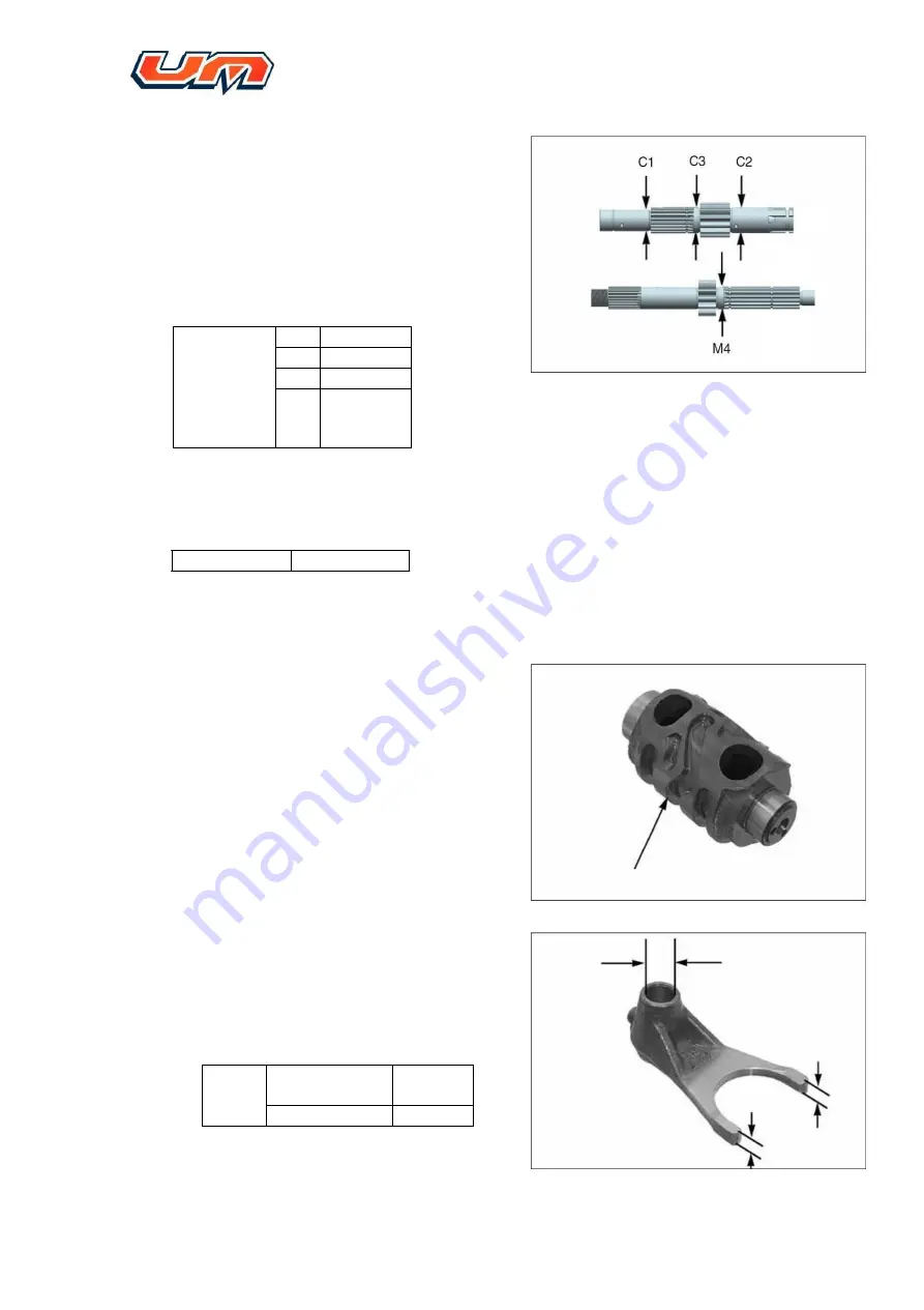
Check   spline   key   and   main   and   counter   shaft   for 
abnormal wear and damage 


Measure 

diameter 

of 

shaft 

at 

gear-matching position. 


Service limit 

of outer 

diameter of 

main and 

counter 

shafts


M4


φ16.93mm


C1


φ16.93mm


C2


φ19.94mm


C3


φ19.95mm


Calculate fit clearance between gears and 
shaft sleeve 


Service limit 

0.10mm 


8.4.5.


Check of gearshift drum 


8.4.5.1.


Check  both  ends  of  gearshift  drum  and 
profiled  groove  for  abnormal  wear  or 
damage 


8.4.5.2.


Check  fork  for  abnormal  wear  and 
deformation 

Measure fork inner hole diameter and ear 
thickness 


Service 

limit


Inner hole 

diameter


10.07mm


Ear thickness


4.50mm


Summary of Contents for CBF 125

Page 1: ...CBF 125 ENGINE AIR COOLING SERVICE MANUAL AND EFI DIAGNOSTIC ...

Page 2: ...L PARAMETERS 2 GENERAL MAINTENANCE 3 LUBRICATION SYSTEM 4 CYLINDER HEAD PARTS MAINTENANCE 5 CYLINDER BLOCK AND PISTON 6 RIGHT COVER CLUTCH BALNACE GEAR GEARSHIFT 7 LEFT COVER STARTING MOTOR SYSTEM MAGNETO 8 CRANKCASE EXTRACTION INSTALATION 9 MIKUNI EFI DIAGNOSTIC SYSTEM XTREET 125 ...

Page 3: ...pression ratio 9 2 1 Valve Timing In Open 5 BTDC Close 37 ABDC Out Open 50 BBDC Close 3 ATDC Max power 7 2 1 5 kW 7500 1 5 rpm Max torque 9 2 1 5 N m 6000 1 5 rpm Idle speed 1400 100 r min Transmission System Clutch Manual wet multi plate Transmission Constant mesh two stage transmission 5 speed gearshift Gearshift method 1 N 2 3 4 5 Primary reduction ratio 3 35 67 20 Gear ratio 1st 3 077 40 13 2n...

Page 4: ...5 Cylinder Head and Valves unit mm Item Standard Service Limit Valve Clearance Inlet 0 04 0 06 Exhaust 0 04 0 06 Valve Stem Diameter Inlet 4 975 4 990 4 92 Exhaust 4 955 4 970 4 90 Valve Guide Internal Diameter Inlet Exhaust 5 000 5 012 5 04 Valve Valve Guide Clearance Inlet 0 010 0 037 0 07 Exhaust 0 030 0 057 0 09 Width of valve sealing strip 0 9 1 1 1 5 Valve Spring Free Length In 38 5 39 5 37 ...

Page 5: ...2 3 Inner diameter of piston pin hole φ14 002 14 008 φ14 04 Closure clearance of piston ring Top 0 1 0 25 0 35 Second 0 15 0 30 0 4 Oil 0 2 0 7 0 85 Piston Ring Groove Clearance Top 0 02 0 06 0 10 Second 0 02 0 06 0 10 Piston Cylinder Clearance 0 01 0 03 0 07 Outer diameter of piston pin φ13 994 φ14 φ13 96 Clearance between piston pin and piston pin hole 0 002 0 014 0 04 Small End of Connecting Ro...

Page 6: ...earance 0 0 008 0 03 Side Clearance 0 1 0 35 0 5 Crankshaft Run out 0 03 0 08 Fork Outer diameter of fork shaft Φ9 966 φ9 984 Φ9 93 Inner diameter of fork Φ10 000 φ10 018 φ10 05 Shift Fork Thickness 4 93 5 00 4 5 Transmission Gears inner hole diameter M4 Φ20 000 φ20 021 Φ20 04 M5 Φ20 000 φ20 021 Φ20 04 C1 Φ20 500 φ20 521 Φ20 55 C2 Φ23 000 φ23 021 Φ23 04 C3 Φ23 025 φ23 046 Φ23 06 Bushing external d...

Page 7: ...ANUAL XTREET 125 EFI 7 GENERAL MAINTENANCE 2 1 ENGINE MAINTENANCE CYCLE 8 2 2 ENGINE MAINTENANCE STANDARDS 8 2 3 TORQUE STANDARS 8 2 4 SPARK PLUG MAINTENANCE 9 2 5 VALVE CLEARANCE ADJUSTMEN 10 2 6 OIL LEVEL INSPECTION 12 2 7 OIL CHANGE 13 ...

Page 8: ...m the fuel filter must be changed every 3000 Km as is specified in the table and the fuel pump filter changed every 10000 km 2 2 Engine Maintenance Standards Item Standard Service Limit Engine oil Specification SJ 10W 40 1 2L Capacity Filter is not removed 1 Oil filter removed 1 1L Dry Engine 1 2 Valve Clearance Inlet 0 04 0 06 mm 0 10mm Exhaust 0 04 0 06 mm 0 15mm Spark Plug Standard CPR8EA 9 NGK...

Page 9: ...ngine If the lateral and center electrode have erosion or covered with accumulation of carbon the spark plug shall be cleaned or replaced The clearance of spark plugs shall be 0 8 1 0 mm Assembly torque of spark plug 16 N m Note A spark plug that does not is properly tighten may cause damage to the engine If the spark plug is too loose it may cause damage to the piston If the spark plug is too tig...

Page 10: ...ne T on rotor of magneto is aligned with center of view hole Remove upper cover of cylinder head refer to 4 2 section Check Valve Clearance Note The inspection and adjustment of the valve clearance shall be checked and adjusted under the cold machine condition of the engine Clearance will change as the engine temperature rises Adjust Valve Clearance Inlet and exhaust valve clearance 0 04 0 06 mm T...

Page 11: ...CBF 125 AIR COOLING ENGINE SERVICE MANUAL XTREET125EFI 11 Tighten caps of large and small view holes respectively Install upper cover of cylinder head and check the engine for leakage ...

Page 12: ...tes 2 6 4 2 3minutes after stopping the engine support the vehicle using the main stand on firm level ground remove oil level gauge wipe it up and reinsert it Then put it out again to check oil level which must be kept between the upper and lower limits on the gauge Make sure there are no oil leaks 2 6 5 If is necessary please add oil until the level reaches upper limit on the gauge Never exceed t...

Page 13: ...th soap and water as soon as possible after handling used oil Changing the oil filter requires a torque wrench If you do not have it or the necessary skill to do the task we recommend you visit your UM dealer to perform this service Change the engine oil with the engine at normal operating temperature and the vehicle stand on its side stand to assure complete and fast draining 2 7 1 Place a drain ...

Page 14: ...on The oil screen shall not be cleaned with gasoline or other solvents that may damage rubber Reinstall the right cover refer to 6 5 section 2 7 11 Check if bolt and sealing washer are in good condition Replace the drain bolt and sealing washer then tighten the bolt Always replace the sealing washer whenever renewing the engine oil Tightening torque engine oil drain bolt 24 N m 2 7 12 Fill the eng...

Page 15: ...G ENGINE SERVICE MANUAL XTREET125EFI 15 LUBRICATION SYSTEM 3 1 Lubrication system schematic diagram 16 3 2 Lubrication system technical specifications 17 3 3 Troubleshooting 17 3 4 Oil pump extraction and installation 18 ...

Page 16: ...CBF 125 AIR COOLING ENGINE SERVICE MANUAL XTREET125EFI 16 3 1 Lubrication system schematic diagram ...

Page 17: ...r and pump body 0 15 Requirements of tightening torque Fastening bolt of oil pump 10N m Screw on cover plate of oil pump 3N m 3 3 Troubleshooting Name of component Type of damage Symptom of component Symptom of engine Remedy Oil pump Excessive wear of inner and outer rotors of oil pump Oil is not pumped freely or no oil is pumped Engine overheats and is insufficient in power Replace the oil pump O...

Page 18: ...Oil pump dismantle 3 4 1 1 Dismantle right cover refer to 6 5 section then remove circlip and take out gears of oil pump 3 4 1 2 Take out the pin and remove fastening bolt of oil pump Take out oil pump 3 4 1 3 Remove the two location pins 3 4 2 Oil pump disassembly 3 4 2 1 Remove set screw from cover plate ...

Page 19: ...roughly 3 4 3 Check of oil pump Note When checking oil pump turn the rotor to measure it at multiple points so as judge it if its wear is beyond service limit If wear measured at any point is beyond the service limit the oil pump shall be replaced with a new one 3 4 3 1 Assemble inner and outer rotors pin shaft pin of the oil pump Check side clearance between outer rotor and casing Service limit 0...

Page 20: ...arance between outer and inner rotors of oil pump Service limit 0 20mm 3 4 3 3 Take out the shaft and pin from the oil pump Use knife straight edge and feeler gauge to measure axial clearance between rotor and casing of the oil pump Service limit 0 15mm 3 4 4 Oil pump installation ...

Page 21: ...of outer rotor and install the rotor into oil pump casing 3 4 4 2 Apply lube oil on the circumference of inner rotor pin shaft and pin and install them into oil pump casing 3 4 4 3 Install cover plate of oil pump and tighten the screw Tightening torque 3 0 N m 3 4 4 4 Install locating pin on the engine ...

Page 22: ... 3 4 4 5 Assemble oil pump and tighten the bolt Assemble the pin 3 4 4 6 Install oil pump gears onto pin shaft and install circlip Apply an appropriate amount of lube oil on the gears 3 4 4 7 Install the cover plate of clutch onto engine refer to 6 5 section ...

Page 23: ...T125EFI 23 CYLINDER HEAD PARTS MAINTENANCE 4 1 CYLINDER HEAD EXPLODED VIEW 24 4 2 UPPER COVER OF CYLINDER HEAD MAINTENANCE 25 4 3 ROCKER ARM SET MAINTENANCE 27 4 4 CYLINDER HEAD SET MAINTENANCE 34 4 5 TENSIONER DEVICE EXTRACTION AND INSTALLATION 40 ...

Page 24: ...CBF 125 AIR COOLING ENGINE SERVICE MANUAL XTREET125EFI 24 4 1 Cylinder Head exploded view ...

Page 25: ... of cylinder head maintenance 4 2 1 Remove two bolts form upper cover of cylinder head 4 2 2 Take out upper cover and corresponding seal gasket 4 2 3 Positioning pin and O ring for removing the oil path 4 2 4 Remove the washer and screw from upper cover of the cylinder head ...

Page 26: ...n it using air gun 4 2 6 Assemble bolts and washers after the head cover is checked Need to be replaced old washer by a new one 4 2 7 Assembly location pin and a new O ring 4 2 8 Clean the sealing ring groove and mount a new cover sealing gasket after that assemble to the cylinder head together ...

Page 27: ...t place install rubber gasket of bolt of cylinder head with mark UP upwards 4 2 10 Assembling head cap upper cover bolts and tighten Tightening torque 10N m 4 3 Rocker arm set maintenance 4 3 1 Disassembling of rocker arm assembly 4 3 1 1 Remove tensioner screws 4 3 1 2 Adjust the tensioning device to the loosened position ...

Page 28: ...SERVICE MANUAL XTREET125EFI 28 4 3 1 3 Remove the fastening bolts from timing sprocket chain 4 3 1 4 Remove the timing sprocket chain Care shall be taken when using a tool to fix the chain to avoid dropping it into the crankcase ...

Page 29: ...25EFI 29 4 3 1 5 Remove AB Nut to take out the ROCKER ARM set 4 3 1 6 Loosen fastening bolt on stop plate and remove the stop plate Then remove camshaft 4 3 1 7 Remove fastening bolt of rocker arm shaft 4 3 1 8 Take out rocker arm shaft and rocker arm ...

Page 30: ...s of camshaft for free rotation 4 3 1 10 Inspect the cam for abrasion Service limit Inlet 31 8 mm Exhaust 31 5mm 4 3 1 11 And check rocker arm shaft for wear Service limit 9 91mm 4 3 1 12 Check rocker arm shaft hole for wear check if rocker arm roller clearance is normal Service limit 10 1mm ...

Page 31: ...ocker arm and rocker shaft in accordance with sequence shown in the illustration 4 3 2 3 Use flat screwdriver to turn rocker arm shaft so verify that screw hole on rocker arm shaft is aligned with through hole on rocker arm bracket Then install fastening bolt manually 4 3 2 4 Confirm that the bolts are installed in the right position then use a torque wrench to tighten bolts with the specified tor...

Page 32: ...nt of SO2 grease into cams 4 3 2 6 Mounting the camshaft into the rocker bracket take special attention to the projected point on flange shall be upward as shown in the figure 4 3 2 7 Mounting stop plate and fastening bolts Tightening torque 10 N m 4 3 2 8 Install the completed rocker arm assembly to cylinder head Be careful to check whether two positioning pins are in good conditions before assem...

Page 33: ... gasket and external surface of nut then install them into rocker arm bracket 4 3 2 10 Tighten AB bolt nut in turns Fastening torque 35N m 4 3 2 11 Follow the preceding steps to adjust the engine to the top death center position TDC 4 3 2 12 Assemble chain and timing sprocket adjust sprocket to position as shown in figure ...

Page 34: ...ning torque 9N m 4 3 2 14 Loosen tensioner device to check if chain is tensioned 4 3 2 15 Replace O ring with a new one and assemble the tensioning screw 4 4 Cylinder head set maintenance 4 4 1 Disassembly of cylinder head 4 4 1 1 dismantling the two bolts connecting cylinder head with cylinder block ...

Page 35: ...2 move the cylinder head assembly 4 4 1 3 Remove the cylinder head seal gasket and the two position pins 4 4 1 4 Use special tooling to dismantle valve collet seat ring valve valve steam seal and valve spring respectively 4 4 1 5 Place the parts dismantled in order ...

Page 36: ...inder head assembly 4 4 2 1 Check the cylinder Head combustion chamber clean the carbon deposit 4 4 2 2 ck valve spring for free length In 37 8 mm Outer 40 8 mm 4 4 2 3 Inspection flatness on end face of cylinder head Service Limit 0 04 mm 4 4 2 4 Wear inspection of Valve stem ...

Page 37: ...37 ...

Page 38: ...I 38 4 4 3 Assembly of Cylinder head set Cylinder head exploded view 4 4 3 1 Assemble the components according to the order of exploded view 4 4 3 2 When installing valve spring care shall be taken that the spring dense coil end shall be directed downwards ...

Page 39: ...sembly shall be subject to air tightness test Next operation shall not be done unless the cylinder head assembly is confirmed air tight 4 4 3 4 Assembly positioning pins and a new cylinder head sealing gasket 4 4 3 5 Install the completed cylinder head assembly 4 4 3 6 Fastening two connecting bolts ...

Page 40: ...NG ENGINE SERVICE MANUAL XTREET 125 EFI 40 4 5 Tensioner device extraction and installation 4 5 1 Remove the screw of the tensioning device 4 5 2 Use the right tools to adjust the tensioning device until loosen position ...

Page 41: ...CBF 125 AIR COOLING ENGINE SERVICE MANUAL XTREET 125 EFI 41 4 5 3 Assembly of Tensioner device 4 5 4 Replace O ring with a new one 4 5 5 Tighten the screw ...

Page 42: ...ING ENGINE SERVICE MANUAL XTREET 125 EFI 42 CYLINDER BLOCK AND PISTON 5 1 CYLINDER BLOCK PISTON EXPLODED VIEW 43 5 2 LIMITS FOR SERVICE 44 5 3 TROUBLESHOOTING 44 5 4 CYLINDER BLOCK PISTON DISASSEMBLY AND INSPECTION 45 ...

Page 43: ...CBF 125 AIR COOLING ENGINE SERVICE MANUAL XTREET 125 EFI 43 5 1 Cylinder block piston exploded view ...

Page 44: ...13 96 Clearance between piston pin and piston pin hole 0 002 0 014 0 04 Small End of Connecting Rod Inner diameter φ14 015 φ14 028 φ14 06 Clearance between small end of connecting rod and piston pin 0 015 0 03 0 10 Tightening torque of AB bolt 11N m 5 3 Troubleshooting 5 3 1 Cylinder pressure is too low or there is no cylinder pressure performance at low speed is not acceptable Severely worn or br...

Page 45: ...4 1 2 Knock cylinder block slightly with rubber hammer to separate cylinder block from crankcase Take out cylinder block upwards Care shall be taken to not damage piston when dismantling cylinder block 5 4 1 3 Remove the location pins and the cylinder block gasket 5 4 1 4 Check AB bolts When replace AB bolts with new ones pay attention to check projection length of the installed AB bolt which shal...

Page 46: ...en at two directions mutually perpendicular at every layer Limit value Φ52 5mm 5 4 2 2 Calculate cylindricity of cylinder bore in accordance with the maximum value measured at the positions Limit value 0 10mm If the measurement exceeds the service limit the cylinder block must be replaced with a new one 5 4 2 3 Test of cylinder body flatness Limit value 0 10mm 5 4 2 4 Check guide plate of chain fo...

Page 47: ... nose pliers to remove circlip of piston pin 5 4 3 3 Remove Piston pin 5 4 3 4 Turn piston rings manually to check if the piston rings can rotate freely on the piston without seizure Use thumbs to increase gap slightly between ends of the piston ring to take out the piston ring Note Do not damage piston and piston ring when taking out piston ring Clean off carbon deposit from piston ring groove us...

Page 48: ...d piston skirt calculate their fit clearance Limit value 0 09mm 5 4 4 3 Diameter inspection of piston pin hole Limit value φ14 04mm 5 4 4 4 Detection of piston pin diameter Limit value φ13 96mm 5 4 4 5 Fit clearance between piston pin and piston pin hole Limit value 0 04mm 5 4 4 6 Diameter detection of pin hole in connecting rod Limit value φ14 06mm 5 4 4 7 Fit clearance between connecting rod and...

Page 49: ...inder block and press them down with piston Check gap of each piston ring with feeler gauge Limit value Top ring 0 40mm Second ring 0 40mm Oil ring 0 85mm 5 4 4 9 heck for clearance between piston ring and ring groove Limit value Top ring 0 10mm Second ring 0 10mm 5 4 4 10 Assembly schematic diagram of piston rings 49 ...

Page 50: ...CBF 125 AIR COOLING ENGINE SERVICE MANUAL XTREET 125 EFI 50 ...

Page 51: ...s must be placed away from each to other by 120 Incorrect assembly of piston rings will directly cause oil burning abnormal wear and tear of piston 5 4 5 piston cylinder block installation When checking cylinder block and piston place a clean cloth at crankcase to guard against dust and stranger bodies fall into crankcase Clean off paper gasket oil and other stranger bodies from matching surface b...

Page 52: ...e circlip otherwise the engine may be damaged Piston pin circlip must be installed to its place Split of circlip shall be alternated away from the installing position on the piston Split of circlip must be kept downwards 5 4 5 2 Install locating pin and new sealing gasket of cylinder block Clean off engine oil from end face of crankcase before installing paper gasket to avoid false cases of oil le...

Page 53: ... XTREET 125 EFI 53 Install guide plate of chain into cylinder block Note Guide plate shall be installed to its place as shown in the figure otherwise the plate may be damaged abnormally Assemble cylinder head and tensioner refer to 4 4 section ...

Page 54: ...ER CLUTCH BALANCED GEAR GEARSHIFT 55 6 2 CLUTCH TECHNICAL SPECIFICATIONS 56 6 3 TIGHTENING TORQUE REQUIREMENTS 56 6 4 TROUBLESHOOTING 56 6 5 RIGHT COVER EXTRACTION AND INSTALLATION 57 6 6 CLUTCH EXTRACTION AND INSTALLATION 60 6 7 GEARSHIFT ARM EXTRACTION INSTALLATION 64 6 8 DRIVEGEAR BALANCINGGEARSHIFTARM EXTRACTIONANDINSTALLATION 67 ...

Page 55: ...CBF 125 AIR COOLING ENGINE SERVICE MANUAL XTREET 125 EFI 55 6 1 Exploded view of right cover clutch balancing gear gearshift ...

Page 56: ... locking nut 45N m Five star plate fastening bolts 12N M Positioning plate fastening Bolts 12N M Clutch lid fastening Bolts 12N m 6 4 Troubleshooting 6 4 1 Clutch does not release or not fully release Control arm improper free travel Damaged control arm declutch bearing or pushing rod Severely deformed drive friction plate of clutch Lock up of separate shaft sleeve separate washer and driven gear ...

Page 57: ...n and installation First drain off oil from engine remove bolts from right cover Remove the paper gasket and positioning pin Check the crankshaft oil seal is intact Removal of right cover Take pushing rod of clutch Use tools to dismantle cotter pin on control arm and take out the spring ...

Page 58: ...mation check iif pushing rod and spring are damaged if they are replace them with new ones Partial assembly of right cover Replace oil seal of control arm with new one Apply appropriate amount of lube oil onto lever of control arm then install the arm into right cover Use tools to knock cotter pin into corresponding hole of control arm ...

Page 59: ... Then install pushing rod of clutch Assembly location pins and new paper gasket Removal clutch gasket and engine oil from crankcase before assembling Assemble right cover bracket bolts First tighten the bolt at locating pin then tighten other bolts alternatively Tightening Torque 10 N m Dismantle the oil filter and gears of oil pump ...

Page 60: ...n 6 6 1 Clutch extraction Dismantle 4 bolts from end cover of clutch then take out end cover of clutch bearing declutch spring Dismantle locknut and washer of clutch Take out upper and lower pressure plate of clutch drive and driven friction plates Take out declutch gasket and outer case of clutch ...

Page 61: ...FI 61 Take out declutch shaft sleeve 6 6 2 Checking of clutch Check bearing of clutch for free rotation Check declutch spring of clutch for damage Measure free length of spring Service limit 40 mm Check retaining groove of pressure plate for abnormal wear ...

Page 62: ... Check driven friction plates flatness Service limit 0 20mm Check outer case of clutch and shaft sleeve for abnormal geometry Measure inner hole diameter of driven gear on outer case Service limit 23 08mm Measure inner and outer diameter in shaft sleeve Service limit Inner diameter 17 04mm Outer diameter 22 93mm Measure main shaft diameter Service limit 16 95mm ...

Page 63: ...ain shaft Apply appropriate amount of lube oil onto gears Assemble outer case and declutch washer New friction plates shall be immersed in engine oil before assembly When assemble central sleeve of clutch care shall be taken to align mark on upper pressure plate with that on lower pressure plate When assemble central sleeve the plate with upmost friction on clutch shall be staggered from the other...

Page 64: ... fix pressure plate and tighten locknut of clutch Tightening torque shall meet specified requirement Tightening torque 45N m Assemble spring and clutch end cover and tighten bolts on the end cover in X sequence Tightenng torque 10 N m 6 6 GEARSHIFT ARM EXTRACTION AND INSTALLATION 6 6 1 Take out gearshift arm components Note Do not fall washer into crankcase ...

Page 65: ...rder 6 6 3 1 Pin 6 6 3 2 Locating plate 6 6 3 3 Locating plate bolt 6 6 3 4 Locating plate spring 6 6 3 5 Washer 6 6 4 Check of gearshift arm Check if lever of arm bends deforms or wears abnormally check spring for damage and break 6 6 5 Assemble locating plate spring bolt and washer Hook of spring shall be snapped into locating plate groove Tightening torque 12N m ...

Page 66: ... star shaped plate Pin holes on the star shaped plate shall be aligned with two cylindrical pins 6 6 7 Tighten bolt on star shaped plate Tightening torque 12 N m 6 6 8 Apply lube oil to gearshift arm shaft 6 6 9 Insert return spring of gearshift arm on locating bolt Rotate gearshift arm to confirm that it is installed to its position ...

Page 67: ...gear Note Do not damage woodruff and circumference of crankshaft when removing drive gear and balancing gear 6 6 2 Drive gear and balancing drive gear Assembly 6 6 2 1 Check woodruff key for looseness or abnormal wear If the key is damaged replace it with a new one 6 6 2 2 When assemble align keyway of balancing drive gear with woodruff key on crankshaft and with timing mark on balancing drive gea...

Page 68: ...ith woodruff key on crankshaft and assemble them Apply appropriate amount of engine oil on gears 6 6 2 5 Assemble oil filter washer locknut 6 6 2 6 Tighten nut to specified torque Tightening torque 64N m 6 6 2 7 Assembly the filter cover and paper gasket finally tighten bolt Tightening torque 4N m ...

Page 69: ...eeve and woodruff key 6 6 3 3 Balancing driven Gear Disassembly and assembly Dismantle circlip washer disc washer flat washer in turn Take out balancing driven gear two springs two buffer rubber bushing Check spring for break and damage Check rubber bushing for hardening damage and deformation Check driven gear hub for wear Check driven gear for damage or wear ...

Page 70: ...tween gear and hub Install buffer rubber bushing on right position on the hub Install driven gear onto the rub Install buffer spring into gear Install washer disc washer washer circlip in turn according to sequence shown in figure Note Disc washer concave face shall be directed toward driven gear ...

Page 71: ...shaft and keyway 6 8 1 2 Align keyway of balancing driven gear with woodruff key on balancing shaft Meanwhile rotate balanced driven gear to align the keyway with timing mark on balancing driven gear 6 8 1 3 Assembly washer and locknut Apply appropriate amount of engine oil onto flange face of the nut 6 8 1 4 Tightening the nut to specified torque Tightening torque 45 N m 6 8 1 5 Assemble right co...

Page 72: ...7 LEFT COVER STARTING MOTOR SYSTEM MAGNETO 7 1 EXPLODED VIEW OF LEFT COVER STARTING MOTOR SYSTEM MAGNETO 73 7 2 LEFT COVER EXTRACTION AND INSTALLATION 74 7 3 STARTING MOTOR SYSTEM EXTRACTION AND INSTALLATION 75 7 4 MAGNETOR STATOR EXTRACTION AND INSTALLATION 81 ...

Page 73: ...CBF 125 AIR COOLING ENGINE SERVICE MANUAL XTREET 125 EFI 73 7 1 Exploded view of left cover starting motor system magneto ...

Page 74: ...n 7 2 1 Take out gearshift switch harness from harness groove 7 2 2 Loosen fastening bolt on left cover and remove left cover 7 2 3 Take out locating pin and paper gasket Assemble locating pin and new paper gasket 7 2 4 Install left cover and tighten fastening bolt in accordance with specified sequence ...

Page 75: ...nsert gearshift switch harness into harness groove on left cover 7 3 Starting motor system extraction and installation 7 3 1 Dismantle left cover and take out shaft sleeve dual gear shaft and dual gear 7 3 2 Dismantle bolt of starting motor 7 3 3 Check O ring condition ...

Page 76: ... Use special tools to dismantle magneto rotor 7 3 5 Check needle bearing woodruff key on crankshaft for damage 7 3 6 Clean off engine oil from tapered face of crankshaft Install magneto rotor and turning the gear on crankshaft thus align keyway with woodruff key 7 3 7 Install washer and locknut ...

Page 77: ...ening torque 65 N m 7 3 9 Replace O ring with a new one Apply appropriate amount of lube oil onto O ring before assembling 7 3 10 Assemble starting motor 7 3 11 Apply appropriate amount of lube oil onto dual gear shaft then assemble dual gear dual gear shaft and shaft sleeve Apply appropriate amount of lube oil onto dual gear teeth ...

Page 78: ...e large starting gear onto magneto rotor then check if the gear can rotate normally making it rotate counterclockwise 7 3 13 Magneto rotor disassembly 7 3 13 1 Use special tools to fix rotor then dismantle rotor bolts 7 3 13 2 Take out overrunning clutch 7 3 13 3 Check holder and wedge block for damage ...

Page 79: ...IR COOLING ENGINE SERVICE MANUAL XTREET 125 EFI 79 7 3 13 4 Check teeth of large starting gear for damage Measure outer diameter of large starting gear Service limit 45 60mm 7 3 13 5 Magneto rotor exploded view ...

Page 80: ...aded hole 7 3 13 8 Apply appropriate amount of fastening adhesive onto threads of bolts then use tools to locate and tighten the bolt Tightening torque 16 N m 7 3 13 9 Install large starting gear onto assembled magneto rotor and rotate gear counterclockwise Gear shall be coated with lube oil properly Ensure that the gear can rotate freely counterclockwise but cannot rotate clockwise ...

Page 81: ...agneto 7 4 3 Install a magneto onto left cover then tighten bolts 7 4 4 Install sensor and tighten bolts Press cable clip of magneto into corresponding position on left cover and tighten bolts Note When assemble magneto cable clip collect the harness into groove to avoid harness damages otherwise a short circuit may be generated Tightening torque of bolt 12N m 7 4 5 Install left cover onto engine ...

Page 82: ...ND INSTALLATION 8 1 CRANKSHAFT EXPLODED VIEW 83 8 2 TECHNICAL SPECIFICATIONS 84 8 3 CRANKSHAFT EXTRACTION 85 8 4 DRIVE TRAIN EXTRACTION AND CHECK 87 8 5 BEARINGS EXTRACTION 90 8 6 BEARINGS INSTALLATION 92 8 7 DRIVE TRAIN ASSEMBLY 93 8 8 CRANKSHAFT CHECK 96 8 9 CRANKCASE INSTALLATION 98 ...

Page 83: ...CBF 125 AIR COOLING ENGINE SERVICE MANUAL XTREET 125 EFI 83 8 1 Crankcase exploded view ...

Page 84: ...ift Fork Ear Thickness 4 93 5 00 4 5 Drive train Gear tooth inner hole diameter M4 Φ20 000 φ20 021 Φ20 04 M5 Φ20 000 φ20 021 Φ20 04 C1 Φ20 500 φ20 521 Φ20 55 C2 Φ23 000 φ23 021 Φ23 04 C3 Φ23 025 φ23 046 Φ23 06 Bushing diameter M4 Φ19 959 φ19 980 Φ19 93 M5 Φ19 959 φ19 980 Φ19 93 C1 Φ20 459 φ20 480 Φ20 41 C2 Φ22 984 φ23 005 Φ22 95 Bushing inside diameter M4 Φ17 000 φ17 018 φ17 04 C1 Φ17 000 φ17 018 ...

Page 85: ...ht cover left cover in accordance with steps described above 8 3 2 Loosen and dismantle fastening bolt on chain guard then take out chain guard tension plate guide plate and chain 8 3 3 Dismantle fastening bolt on pressing pin body then take out guard plate of pressing pin body 8 3 4 Take out pressing pin body and spring 8 3 5 Remove circlip and washer on counter shaft ...

Page 86: ...rankshaft 8 3 7 Dismantle fastening bolts on crankshaft 8 3 8 Place crankcase properly with right half downwards Knock counter shaft and crankshaft with rubber hammer to loosen adhesive on halves left and right Place horizontally the crankcase and remove left half upwards 8 3 9 Dismantle location pins ...

Page 87: ...n tension plate for severe wear or damage If there is replace the tension plate with a new one 8 4 Drive train extraction and check 8 4 1 Take out fork shaft of main and counter shafts 8 4 2 Take out fork and gearshift drum from both sides 8 4 3 Take out main and counter shafts ...

Page 88: ...the gears Service limit M4 Φ20 04mm M5 Φ20 04mm C1 Φ20 55mm C2 Φ23 07mm C3 Φ23 07mm 8 4 4 3 Check shaft sleeve for severe wear and damage Measure inner and outer diameters of shaft sleeve Bushing outer diameter service limit M4 Φ19 93mm M5 Φ19 93mm C1 Φ20 41mm C2 Φ22 95mm Bushing inner diameter service limit M4 φ17 04mm C1 φ17 04mm C2 Φ20 04mm Calculate fit clearance between shaft sleeve and gear ...

Page 89: ...nd counter shafts M4 φ16 93mm C1 φ16 93mm C2 φ19 94mm C3 φ19 95mm Calculate fit clearance between gears and shaft sleeve Service limit 0 10mm 8 4 5 Check of gearshift drum 8 4 5 1 Check both ends of gearshift drum and profiled groove for abnormal wear or damage 8 4 5 2 Check fork for abnormal wear and deformation Measure fork inner hole diameter and ear thickness Service limit Inner hole diameter ...

Page 90: ...nd damage 8 4 6 Replacement of bearings 8 4 6 1 Turn inner race of bearing to check if it can rotate freely 8 4 6 2 Check bearing cage and balls looking for severe wear and damage 8 5 Bearings extraction 8 5 1 Dismantle bearing guard and bolts 8 5 2 Take out bearing from right half using a bearing puller ...

Page 91: ...F 125 AIR COOLING ENGINE SERVICE MANUAL XTREET 125 EFI 91 8 5 3 Dismantle counter shaft and gearshift arm oil seals located on left half 8 5 4 Dismantle bearings from left half using a bearing puller tool ...

Page 92: ...holes with special tools Note 1 Bearing shall be installed using special tools 2 When pressing bearing force shall be applied on outer race of bearing otherwise the bearing may be damaged 8 6 2 Apply appropriate amount of lube oil onto inner and outer races then use special tools to press oil seal to its position 8 6 3 Install locating plate of bearings and tighten the bolts to specified torque ...

Page 93: ...o inner and outer races of bushing to guarantee initial lubrication 8 7 4 Install the components and parts onto their original positions Note All gears assembled shall be able to rotate and move freely Washers must be installed in accordance with specified direction Circlip must be replaced with a new one Used circlip has less resilience regards a new one causing looseness After the circlip is ins...

Page 94: ...CBF 125 AIR COOLING ENGINE SERVICE MANUAL XTREET 125 EFI 94 8 7 5 Main shaft Exploded view 8 7 6 Counter shaft exploded view ...

Page 95: ...ot miss washers at both ends of the shafts 8 7 9 Marks on forks C Main shaft fork R L Counter shaft fork 8 7 10 Install forks of counter and main shafts into corresponding positions Face of fork with mark shall be directed upwards Apply appropriate amount of lube oil onto profiled groove of gearshift drum Install gearshift drum into right half of crankcase and install fork into gearshift along dru...

Page 96: ...ck if all components and parts are installed in the right positions and main and counter shafts can rotate freely 8 8 Crankshaft check 8 8 1 Dismantle balanced shaft 8 8 2 Dismantle crankshaft 8 8 3 Check of crankshaft Rest crankshaft on V shaped steel stand Calibrate dial gauge to be used for check Rotate crankshaft to take the maximum reading change on the gauge Service limit 0 08mm ...

Page 97: ...ming drive sprocket on crankshaft for abnormal wear and damage If there is check correspondingly timing driven sprocket chain tensioner etc for abnormal condition When it is necessary to replace timing drive sprocket tooth crown of drive sprocket shall be aligned with center of crankpin 8 8 6 Check balanced shaft for abnormal wear Replace it with a new one if is necessary 8 8 7 Check if bearing ca...

Page 98: ...kcase installation 8 9 1 Install crankshaft into right half of crankcase 8 9 2 Install balanced shaft 8 9 3 Clean matching faces on left and right halves of crankcase Apply sealing adhesive on matching face of left half as shown in the figure 8 9 4 Install location pins ...

Page 99: ...onto their positions and if there are foreign elements in the crankcase 8 9 6 Install and approximate the bolts then tighten them with torque spanner to specified torque Tightening torque 12N m Note After the bolts are tightened check main and counter shafts crankshaft balanced shaft for free rotation Tighten 4 bolts inside left cover first then tighten the other bolts crosswise 8 9 7 Tighten bolt...

Page 100: ...ing 8 9 10 Apply adhesive to thread on 2 3 of length then install pressing pin body guard and bolts onto crankshaft case Tighten the bolts to specified value Tightening torque 10N m 8 9 11 Install chain tension plate chain guard plate in this order then tighten bolts CBF 125 AIR COOLING ENGINE SERVICE MANUAL XTREET 125 EFI ...

Page 101: ... 125 AIR COOLING ENGINE SERVICE MANUAL XTREET 125 EFI 101 9 MIKUNI EFI DIAGNOSTIC SYSTEM XTREET 125 EFI 9 1 GENERAL INFORMATION 102 9 2 STEPS TO MAKE THE DIAGNOSTIC 102 9 3 OBD II STANDARD FAULT CODES 107 ...

Page 102: ...ooth It is compliant with OBD II EOBD specification It reads the recorded data on the car or motorcycle ECU by the iOBD2 app When the car or motorcycle is running it reads the real time engine data such as engine speed ignition time fuel trim water temperature etc 9 2 Steps to make the diagnostic Installation of IOS version Install by Smartphone Open the App store and search iOBD2 download the app...

Page 103: ...r into the OBD II port on the motorcycle and turn the ignition switch on without starting the engine The OBD II port is located below the front seat but it may be variance on different motorcycle models Image shows 9 the OBD II location below the seat and connection 10iOBD2 adapter 11 Right conection between OBD II and iOBD2 Open the app Click to open the iOBD2 application the interface of the app...

Page 104: ...essful logo to appear Note With the XTOOL adapter you can only use some of Diagnostic and Dashboard options Trouble codes You can use Diagnostic to scan and read all failure codes Trouble Code If a failure code is showed on the screen please check the related circuit for proper solution ...

Page 105: ...URE P0505 508 IDLE AIR CONTROL SYSTEM FAILURE P0628 FUEL PUMP FAILURE P2300 IGNITION COIL LOW VOLTAGE CIRCUIT FAILURE Note Please refer to 9 3 section to see the complete list of all standard OBD2 failure codes Erasing trouble codes If a trouble code was solved and need to be erased press the Clear Trouble Code button and Follow the instructions Once erase a trouble code please ignition off and th...

Page 106: ...u can use Live Data to read in real time some of the sensors of the system The picture below shown A All the sensors to read Press Done B Information about the selected sensors Dashboard In Dashboard you can see real time bike variables Engine Speed RPM Coolant temperature ignition timing ...

Page 107: ...Sensor 1 P0133 O2 Sensor Circuit Slow Response Bank 1 Sensor 1 P0134 O2 Sensor Circuit No Activity Detected Bank 1 Sensor 1 P02XX Fuel and Air Metering P0200 Injector Circuit Malfunction P0216 Injection Timing Control Circuit Malfunction P0217 Engine Over Temperature Condition P0230 Fuel Pump Primary Circuit Malfunction P0231 Fuel Pump Secondary Circuit Low P0232 Fuel Pump Secondary Circuit High P...

Page 108: ...gramming Error P0603 Internal Control Module Keep Alive Memory KAM Error P0604 Internal Control Module Random Access Memory RAM Error P0605 Internal Control Module Read Only Memory ROM Error Module Identification Defined by SAE J1979 P0606 PCM Processor Fault P0620 Generator Control Circuit Malfunction P0621 Generator Lamp L Control Circuit Malfunction P0622 Generator Field F Control Circuit Malfu...

Reviews: