background image

17

18

CALIBRATION

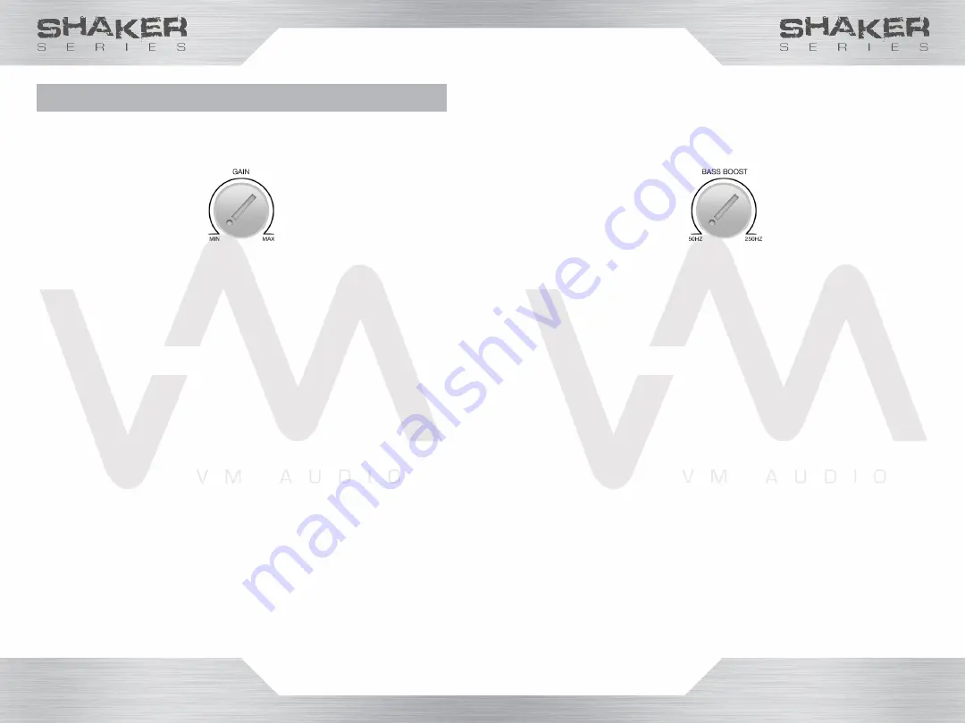
Setting Gain

1. Turn the gain and bass control all the way 

down (counterclockwise).

2. Turn the vehicle on, and make sure the source 

unit is turned on.

3. Insert a CD/DVD with undistorted music.

4. Start to increase the volume at the source unit 

until you hear distortion (aproximately at 90%).

5. Turn the volume down at the source unit until 

the distortion goes away.

6. At the amplifier, slowly turn the Gain control 

up (clockwise) until you hear a slight audio 

distortion.

7. Turn the Gain control back down until the audio 

distortion goes away.

8. When the Gain control is properly set, you 

should be able to achieve the maximum 

undistorted output with the volume turned all 

the way up.

Warning!

Do not set the amplifier’s gain very high as noise, 

distortion and amplifier heat will increase significantly 

and amplifier failure could occur. 

If Bass Boost is used, keep the Gain setting down.

Setting Bass Boost

1. Turn the gain and bass control all the way 

down (counterclockwise).

2. Turn the vehicle on, and make sure the source 

unit is turned on.

3. Insert a CD/DVD with undistorted music.

4. Start to increase the volume at the source unit 

until you hear distortion (aproximately at 90%).

5. Turn the volume down at the source unit until 

the distortion goes away.

6. At the amplifier, slowly turn the Bass Boost 

control up (clockwise) until you hear a slight 

distortion from the speakers.

7. Turn the Bass Boost control back down until 

the distortion goes away.

8. When the Bass Boost control is properly set, 

you should be able to achieve the maximum 

undistorted output with the volume turned all 

the way up.

Warning!

Do not set or increase the amplifier’s gain when setting 

the Bass Boost control. Increasing the gain even slightly 

will cause the amplifier to heat up and amplifier failure 

could occur.

Summary of Contents for SRA1000.2

Page 1: ...SRA500 2 SRA850 2 SRA1000 2 SRA1550 2 SRA1800 2 2 CHANNEL AMPLIFIERS ...

Page 2: ... the value of your investment Class A B Amplifiers Low Noise and Distortion Bridgeable Outputs DC to DC PWM Conversion Unbalanced Inputs Soft Turn On Discrete Signal Processing Preamp Stereo Outputs Amplifier Protection Circuits Variable Gain Control Lowpass Active Crossover Highpass Active Crossover Bypass Crossover Frequency Variable Crossovers Bass Boost Gain FEATURES INTRODUCTION FEATURES FUNC...

Page 3: ...s Adjustment Knob 5 LPF Low Frequency Filter Adjustment Knob 6 FLT Bypass Crossover Selection 7 HPF High Frequency Filter Adjustment Knob 8 LED Power Status LED FUNCTIONS Rear Panel 9 POWER INPUT Power Cable Terminal 10 FUSE In Line Protection Fuse s 11 SPEAKER OUTPUT Speaker Wire Terminal 1 2 3 4 5 6 7 9 10 11 8 SRA500 2 Shown SRA500 2 Shown ...

Page 4: ...he engine compartment 5 6 GETTING STARTED Wiring Before you begin routing and connecting the power wires disconnect the negative ground cable from the vehicle s battery Install and connect the highest possible wire gauge the amplifier s terminal will accept 1 0 GAUGE for both power cables 12V and GND Install an in line fuse into the positive wire 18 inches away from the car battery It should be th...

Page 5: ...connect the negative battery terminal before routing cables and wires to prevent electrical shorts 1 Strip 1 2 inch of insulation off each end of the power cables 2 Connect one end of the power cable to the positive battery post 3 Install an in line fuse holder 18 inches away from the car battery 4 Route the power cable from the battery to the in line fuse holder and connect 5 Route the power cabl...

Page 6: ... the amplifier automatically when your stereo is turned on Consult with the manufacturers user guide for your stereo head unit to locate the remote or turn on wire as some manufacturer s might label their amplifier turn on feature differently GROUND 1 Locate a good non rusted chassis metal point in the vehicle 2 Mark and drill a screw hole with an electric drill where chassis ground connection is ...

Page 7: ...must be used Both line inputs need to be connected to the stereo head unit in order to use all of the speaker outputs Linking Amplifier The pre amp line outputs allow linking additional amplifiers without the need to split the audio signals from the stereo using Y RCA cable adaptors Stereo RCA Cables Speaker Wires High to Low Level Converter not included Left Channel Right Channel Right Channel Le...

Page 8: ...t channel and the other speaker to the left channel 80 Hz Amplifier Crossover Settings HPF Component Speaker Wiring Observing polarity Connect one speaker to the right channel and the other speaker to the left channel Amplifier Crossover Settings FLT 2Ω 4Ω SPEAKER IMPEDANCE 2Ω 4Ω SPEAKER IMPEDANCE ...

Page 9: ... Increases the bass level from 1dB up to 18dB LPF Low pass filter that reduces the signal level of frequencies above the bass region FLT Crossover setting that disables and bypasses the internal crossover HPF High pass filter that reduces the signal level of frequencies below the bass region LPF Frequency Low pass crossover frequency filter adjustment HPF Frequency High pass crossover frequency fi...

Page 10: ...e significantly and amplifier failure could occur If Bass Boost is used keep the Gain setting down Setting Bass Boost 1 Turn the gain and bass control all the way down counterclockwise 2 Turn the vehicle on and make sure the source unit is turned on 3 Insert a CD DVD with undistorted music 4 Start to increase the volume at the source unit until you hear distortion aproximately at 90 5 Turn the vol...

Page 11: ...REDUCED BASS 1 Speakers may be wired in reverse polarity Reverse a speaker connection from positive to negative on the stereo or speaker AMPLIFIER FUSE KEEPS BLOWING 1 Incorrect wiring or short circuit Using your DMM make sure that all voltage polarities are correct Review section Installation for proper wire connection 2 Amplifier being driven too hard Turn down the volume Gain or Bass Boost not ...

Page 12: ... 0dB 12dB 200mV 8V 22k Ω 90dB 60dB 30A 9 40 9 94 2 40 SRA1000 2 2 250W 500W 1000W 0 05 20Hz 25kHz 50 250Hz N A 0dB 12dB 200mV 8V 22k Ω 90dB 60dB 40A 10 17 9 94 2 40 MODELS OUTPUT CHANNELS POWER per channel 4Ω 2Ω 4Ω Bridged THD N 4Ω FREQ RESPONSE LOWPASS SUBSONIC BASS BOOST INPUT SENSITIVITY INPUT IMPEDANCE S N RATIO CH SEPARATION FUSE DIMENSIONS WIDTH inches HEIGHT inches DEPTH inches SRA1550 2 2 ...

Page 13: ...edy claim of your warranty service Contact VM Audio directly to find the Authorized Dealers nearest you In the case the defective merchandise needs to be returned to VM Audio please contact us and a Return Merchandise Authorization RMA number will be assigned It is important to pack all defective items in the original packaging to prevent damages from shipping and be sure to write the RMA number c...

Reviews: