background image

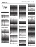
Proton

0178

Pulsar

0017, 0019

Quasar

0051, 0250

RCA

0047, 1347, 1147, 0679, 1247, 0019,
0051, 0090, 0093, 1047, 1447

RadioShack

0180, 0030, 0178, 0154, 0019, 0047,
0056

Realistic

0180, 0154, 0030, 0178, 0019, 0056

Runco

0017, 0030

SSS

0019, 0180

Sampo

0030

Samsung

0060, 0019, 0178, 0030, 0056

Sansei

0451

Sansui

0463

Sanyo

0154

Scimitsu

0019

Scotch

0178

Scott

0236, 0019, 0178, 0179, 0180

Sears

0154, 0056, 0156, 0047, 0054, 0171,
0178, 0179

Semivox

0180

Semp

0156

Sharp

0093, 0688

Shogun

0019

Signature

0016

Sony

0000

Soundesign

0178, 0179, 0180

Squareview

0171

Starlite

0180

Supreme

0000

Sylvania

0054, 0030

Symphonic

0171, 0180

TMK

0056, 0178

TNCi

0017

Tandy

0093

Technics

0051, 0250

Technol Ace

0179

Techwood

0051, 0056

Teknika

0016, 0054, 0179, 0180, 0019, 0092,
0056, 0060, 0150

Telefunken

0056

Toshiba

0156, 0060, 0154, 1256

Vector Research

0030

Victor

0053

Vidikron

0054

Vidtech

0019, 0178

Wards

0054, 0178, 0016, 0019, 0030, 0056,
0179

White Westinghouse 0624, 0623, 0463
Yamaha

0019, 0030

Zenith

0017, 0624, 0016, 0092, 0463

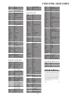
Setup Codes for TV/VCR Combos:

American High

0035 (for TV use 0051) 

Brocksonic

0002, 0294,

Colt

0072 

Curtis Mathis

0035 (for TV use 0051) 

Daewoo

0278 

Emerson

0002, 0294, 0479                                    

Funai

0000 

GE

0035 (for TV use 0051),
0060 (for TV use 0047),
0048 (for TV use 0093), 0240 

Hitachi

0035 (for TV use 0051), 0000 

HQ

0000 

Lloyds

0000                                                         

MGA

0240                                                         

Magnavox

0081 (for TV use 0054),
0035 (for TV use 0051), 0000 

Magnin

0240 

Memorex

0037, 0162 (for TV use 0250) 

Mitsubishi

0048 (for TV use 0093)

Orion

0002, 0294, 0479

Panasonic

0035 (for TV use 0051),
0162 (for TV use 0250)

Penney

0035 (for TV use 0051), 0240,
0162 (for TV use 0250)

Quasar

0035 (for TV use 0051),

0162 (for TV use 0250)

RCA

0060 (for TV use 0047),
0035 (for TV use 0051),
0048 (for TV use 0093)

Sansui

0000, 0479

Sanyo

0240

Sears

0000, 0037

Sharp

0048 (for TV use 0093)

Sony

0032 (for TV use 0000)

Symphonic

0000

Zenith

0000

Setup Codes for VCRs:

Admiral

0048, 0209

Adventura

0000

Aiko

0278

Aiwa

0000, 0037

America Action

0278

American High

0035

Asha

0240

Audiovox

0037

Beaumark

0240

Bell & Howell

0104

Broksonic

0121, 0184, 0002, 0209, 0479

CCE 0072,

0278

Calix

0037

Canon

0035

Carver

0081

Cineral

0278

Citizen

0278, 0037

Colt

0072

Craig

0037, 0072, 0047, 0240

Curtis Mathes

0035, 0060, 0162

Cybernex

0240

Daewoo

0278, 0045

Denon

0042

Dynatech

0000

Electrohome

0037

Electrophonic

0037

Emerex

0032

Emerson

0184, 0002, 0209, 0278, 0121, 0479,
0000, 0037, 0043

Fisher

0047, 0104

Fuji

0033, 0035

Funai

0000

GE

0035, 0060, 0048, 0240

Garrard

0000

Go Video

0432

GoldStar

0037, 0038

Gradiente

0000

HI-Q

0047

Harley Davidson

0000

Harman/Kardon

0038, 0081

Harwood

0072

Hitachi

0042, 0000

Hughes Net. Sys.

0042

JVC

0067

KEC

0037, 0278

KLH

0072

Kenwood

0067, 0038

Kodak

0035, 0037

LXI

0037

LloydÕs

0000

Logik

0072

MEI

0035

MGA

0043, 0240

MGN Technology

0240

MTC

0000, 0240

Magnasonic

0278

Magnavox

0035, 0081, 0563, 0000, 0039, 0149

Magnin

0240

Marantz

0081, 0035

Marta

0037

Matsushita

0035, 0162

Memorex

0104, 0047, 0479, 0000, 0037, 0048,
0035, 0240, 1037, 0039, 0162, 0209,
1162, 1262

Minolta

0042

Mitsubishi

0043, 0048, 0067

Motorola

0035, 0048

Multitech

0000, 0072

NEC

0038, 0067, 0104

Nikko

0037

Noblex

0240

Olympus

0035

Optimus

0162, 1062, 1162, 0048, 1262, 0037,
1048, 0104, 0432

Orion

0479, 0002, 0184, 0209

Panasonic

0035, 0162, 1162, 1262, 1362, 0616,
1062

Penney

0035, 0240, 0037, 0042, 0038

Pentax

0042

Philco

0035, 0209, 0479

Philips

0081, 0035, 0618, 1081, 1181

Pilot

0037

Pioneer

0067

Polk Audio

0081

Profitronic

0240

Proscan

0060

Protec

0072

Pulsar

0039

Quasar

0035, 0162, 1162

RCA

0060, 0149, 0042, 0035, 0048, 0240

RadioShack

0000, 1037

Radix

0037

Randex

0037

Realistic

0000, 0104, 0047, 0048, 0037, 0035

ReplayTV

0614, 0616

Runco

0039

STS

0042

Samsung

0045, 0240

Sanky

0039, 0048

Sansui

0479, 0000, 0067, 0209

Sanyo

0047, 0104, 0240

Scott

0184, 0121, 0043, 0045

Sears

0037, 0042, 0000, 0035, 0047, 0104

Semp

0045

Sharp

0048

Shintom

0072

Shogun

0240

Singer

0072

Sony

0033, 0032, 0000, 0035, 0636, 1032

Sylvania

0035, 0081, 0000, 0043

Symphonic

0000

TMK

0240

Teac

0000

Technics

0035, 0162

Teknika

0000, 0035, 0037

Thomas

0000

Tivo

0618, 0636

Toshiba

0045, 0043

Totevision

0037, 0240

Unitech

0240

Vector

0045

Vector Research

0038

Video Concepts

0045

Videosonic

0240

Wards

0035, 0060, 0000, 0047, 0240, 0042,
0048, 0072, 0081, 0149

White Westinghouse 0072, 0278, 0209
XR-1000

0072, 0000, 0035

Yamaha

0038

Zenith

0039, 0000, 0033, 0209, 0479

Setup Codes for Video Accessories:

Panasonic

1120

Pioneer

1010

Sensory Science

1126

Sharp

1010

ADDITIONAL INFORMATION

The Catalyst 48 does not have any user-serviceable
parts. Opening the case, except for the battery cover,
may cause permanent damage to your Catalyst 48.

©2003 by Universal Electronics, Inc. No part of this
publication may be reproduced, transmitted, tran-
scribed, stored in any retrieval system, or translated
to any language, in any form or by any means, elec-
tronic, mechanical, magnetic, optical, manual, or
otherwise, without the prior written permission of
Universal Electronics, Inc.

M4800 03/04

VIZIO RP56 User Guide

54

Summary of Contents for RP56 - 56" Rear Projection TV

Page 1: ......

Page 2: ...ox 17 Connecting your VCR or Video Camera 20 Connecting Coaxial RF 22 Connecting External Amplified Speakers 24 Connecting an External Receiver or Amplifier 25 Connecting a Computer 26 3 Getting Start...

Page 3: ...d 40 4 Maintenance and Troubleshooting 41 Safety Guidelines 41 Compliance 42 Television Antenna Connection Protection 43 Cleaning Maintenance 44 Cleaning the Screen 44 Cleaning the Exterior 44 Replaci...

Page 4: ...HDCP will be used for HD Programs and Movies and the HDTV needs this feature to be able to display the picture Two HD Component Video inputs automatically synchronize to the input Compatible with HDT...

Page 5: ...s on the DLP TV The DLP TV should be operated only from the type of power source indicated on the label If you are not sure of the type of power supplied to your home consult your dealer or local powe...

Page 6: ...VIZIO RP56 User Guide 040330 3 Package Contents V Inc Rear Projection DLP TV Power cord Universal Remote control with two AA batteries PIP Remote Control with two AAA batteries This User Guide...

Page 7: ...of the inputs you will return to the input you started at Menu and Exit Pressing this button activates the On Screen Display OSD and shows the Main Menu Pressing this button again exits closes the OSD...

Page 8: ...Theater receiver Composite AV Connectors Connect to a VCR or DVD player Component AV Connectors Connect to a DVD player or set top box PC Audio Connector Connect the audio from a computer or set top...

Page 9: ...until latches clicks shut S Video Connect to a video camcorder Video Audio In Connect to audio video equipment such as a video camcorder or digital camera Headphones Connect your headphones to MAIN to...

Page 10: ...ote Control to operate TV is pre programmed to operate your DLP TV DVD selects a programmed DVD Player VCR selects a programmed VCR TV2 selects a second programmed TV CBL SAT selects a programmed cabl...

Page 11: ...onent buttons tells the VCR CD or DVD player to rewind PIP Turn on or off the PIP Picture In Picture or POP Picture On Picture mode When chosen with one of the Component buttons tells the VCR CD or DV...

Page 12: ...re will not return to the same point as when it was frozen PIP SCAN Turn on or off PIP Scan when in the multi PIP mode When turned on the screen is split into a grid of twelve equal size pictures the...

Page 13: ...00 button first CH U V Change the channel in the PIP window VOL U V Increase or decrease the audio volume for the PIP window SIZE Increase or decrease the size of the PIP window SWAP Swap the main pic...

Page 14: ...off Align the batteries for the correct polarity shown in the case Replace the cover by locating the tabs and closing it down on the latch PIP Remote Control Battery Installation and Replacement When...

Page 15: ...S Video The video signal is separated into two signals one containing the black and white information and the other containing the color information Separating the color in this way avoids cross colo...

Page 16: ...ayer 2 Connect a DVI D cable to the DVI output of your DVD player and the other end to the DVI input in the rear of your DLP TV 3 Connect the Audio Out Left Right on your DVD player to the DVI Audio I...

Page 17: ...lor connector in the COMP 1 IN group on the rear of your DLP TV 5 Connect the R red color and L white color audio connectors on the rear of your DVD player to the R red color and L white color compone...

Page 18: ...color and L white color component audio input connectors in the AV 2 IN group on the rear of your DLP TV 4 Turn on the power to the DLP TV and DVD player 5 Select AV 2 using the INPUT button on the fr...

Page 19: ...player to the R red color and L white color component audio input connectors in the AV 2 IN group on the rear of your DLP TV 4 Turn on the power to the DLP TV and DVD player 5 Select AV 2 using the IN...

Page 20: ...your HDTV Set Top Box and the other end to the DVI input in the rear of your DLP TV 3 Connect the Audio Out Left Right on your HDTV Set Top Box to the DVI Audio In L White and R Red in the rear of you...

Page 21: ...2 IN group on the rear of your DLP TV 5 Connect the R red color and L white color audio connectors on the rear of your HDTV Set Top Box to the R red color and L white color component audio input conn...

Page 22: ...TV 3 Connect the Audio Out Left Right on your HDTV Set Top Box to the RGB Audio In Stereo Mini Jack in the rear of your DLP TV next to the RGB connector 4 Turn on the power to the DLP TV and your HDT...

Page 23: ...color and L white color component audio input connectors in the AV 1 IN group on the rear of your DLP TV 4 Turn on the power to the DLP TV and VCR or video camera 5 Select AV 1 using the INPUT button...

Page 24: ...a to the R red color and L white color component audio input connectors in the AV 1 IN group on the rear of your DLP TV 4 Turn on the power to the DLP TV and VCR or video camera 5 Select AV 2 using th...

Page 25: ...nector on the rear of your DLP TV 3 Turn on the power to the DLP TV and VCR 4 Select TV using the INPUT button on the front of the DLP TV 5 Select Channel 3 or 4 to match the channel selected on the r...

Page 26: ...he DLP TV 2 Connect the coaxial RF connector from your antenna or cable box to the TV CABLE IN connector on the rear of your DLP TV 3 Turn on the power to the DLP TV 4 Select TV using the INPUT button...

Page 27: ...T group on the rear of your DLP TV 3 Turn on the power to the DLP TV and speakers 4 Press the MENU button on the front of your DLP TV or on the remote control to activate the On Screen Display OSD 5 P...

Page 28: ...ectors in the AUDIO OUT group on the rear of your DLP TV 3 Turn on the power to the DLP TV and receiver or amplifier 4 Press the MENU button on the front of your DLP TV or on the remote control to act...

Page 29: ...Audio In L White and R Red in the rear of your DLP TV next to the DVI connector 4 Turn on the power to the DLP TV and your computer 5 Select DVI using the INPUT button on the front of the DLP TV Note...

Page 30: ...ut in the rear of your DLP TV 3 Connect the Audio Out mini jack on your computer to the RGB Audio In L White and R Red in the rear of your DLP TV next to the RGB connector 4 Turn on the power to the D...

Page 31: ...el is reached To decrease the volume press and hold the VOL button on the front panel or Remote Control until the desired level is reached TV Channels To step up through the available TV channels pres...

Page 32: ...f the feature selected 4 Press the TADJUST CH or ADJUST S CH button on the front panel to highlight the option you wish to adjust and press the OK button on the front panel 5 Adjust the level or chang...

Page 33: ...TYLE Turns PIP mode on or off or chooses one of the following pre set modes SPLIT The screen is divided in half The left side is the main picture and the right side is the sub picture POP The screen i...

Page 34: ...captioning on and off AUTO automatically turns captioning on when the DLP TV is muted CAPTION STYLE Sets the display style for closed captioning AUDIO ADJUST BASS Adjusts the bass TREBLE Adjust the t...

Page 35: ...layed before it automatically turns off COLOR TEMPERATURE Adjusts the color temperature to three preset modes Select COOL NEUTRAL or WARM LANGUAGE Chances the language of the OSD menu Select ENGLISH F...

Page 36: ...WAP button again and the pictures will switch back again o When the PIP window is visible press the STYLE button and the DLP TV will show the main and sub pictures as a split screen with the screen be...

Page 37: ...e correct one for your component Note If you cannot find your manufacturer in the component list or if none of the programming codes work you can use the Remote Control to search for the correct compo...

Page 38: ...s on the remote control if you have more than one of the same type of component Example If you are using the Universal Remote to control your cable CBL CD DVD TV and two VCRs you can reassign the sate...

Page 39: ...he LED flashes quickly while it is waiting to receive the signal from the teaching remote 5 Hold the teaching remote control approximately 1 inch 25mm from the Universal Remote Control making sure tha...

Page 40: ...in turn becomes live for a few seconds after which it freezes while the other two take their turn in being live Press the STYLE button again and the format will change to Main 7 mode which means ther...

Page 41: ...SLEEP button again to set the turn off time to 120 minutes Pressing the SLEEP button one more time will set the timer to 0 turn off the sleep time To turn off the sleep timer using the universal remo...

Page 42: ...ss the OK button to open the TV RATINGS menu 13 Press the buttons to select which rating you want to block or unblock You can select from the following ratings TV Y all children TV Y7 older children T...

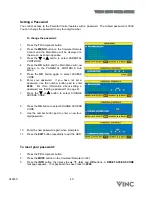
Page 43: ...Press the OK button again to select ACCESS CODE 6 Enter your password If you have not set a password use the number button pad to enter 0000 For more information about setting a password see Setting a...

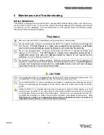
Page 44: ...maged contact V Inc Do not stand on tilted or unstable surfaces Doing so could cause the DLP TV could fall over resulting in a broken screen and DLP Engine and possibly personal injury The DLP Engine...

Page 45: ...ticular installation If this equipment does cause harmful interference to radio or television reception which can be determined by turning the equipment off and on the user is encouraged to try to cor...

Page 46: ...oper grounding of the mast and supporting structure grounding of the lead in wire to an antenna discharge unit size of grounding conductors location of antenna discharge unit connection to grounding e...

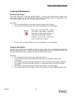
Page 47: ...Do not scratch or hit the surface of the screen with fingers or any hard objects Cleaning the Exterior The DLP TV is cooled by air circulated through the vents in the case so for optimized performanc...

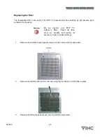
Page 48: ...lamp Do not operate your DLP TV without a filter Check the filter every six months and replace as necessary to prevent heat damage 1 Remove the two filter access panel screws and then remove the acce...

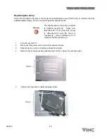
Page 49: ...lamp may explode if handled incorrectly Make sure that the DLP TV is turned off power is disconnected and the lamp is completely cooled minimum of 45 minutes before replacing it 1 Turn off your DLP TV...

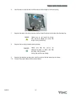
Page 50: ...lamp bay Make sure to not touch the lamp The oils from hands can cause the lamp to fail prematurely 8 Replace the two lamp module retaining screws Make sure that the screws are fastened securely to m...

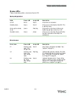
Page 51: ...ected the power button has been pressed and the lamp has warmed up Error Codes Error Code Power LED Lamp LED Description 21 Flashes green twice then orange once Not lit One of the cooling fans has fai...

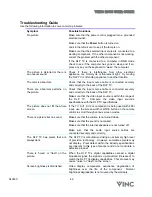
Page 52: ...sure that the video input source is within the range of the DLP TV Compare the video input source s specifications with the DLP TV specifications The picture does not fill the whole screen If the TV A...

Page 53: ...al Remote Control on pager 34 Make sure that you tried all the program codes listed for the component manufacturer See Appendix B Component Program Codes on page 54 Search for the component code See S...

Page 54: ...warranty period please contact our Support Department at the number below Quality service and consistent technical support are integral parts of V s commitment to service excellence V s service repre...

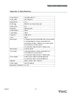
Page 55: ...plus 1x Stereo Audio 1x Analog RGB plus 1x Stereo Audio Mini Jack 2x Component Video YPbRr plus 1x Stereo Audio 2x S Video plus 1x Stereo Audio 2x Composite Video AV plus 1x Stereo Audio Rear Output...

Page 56: ...630 Sony 0533 Technics 0490 Theta Digital 0571 Toshiba 0503 Yamaha 0490 0545 Zenith 0591 0503 Setup Codes for Home Automation GE 0240 One ForAll 0167 Radio Shack 0240 Security System 0167 Universal X1...

Page 57: ...Fisher 0047 0104 Fuji 0033 0035 Funai 0000 GE 0035 0060 0048 0240 Garrard 0000 GoVideo 0432 GoldStar 0037 0038 Gradiente 0000 HI Q 0047 Harley Davidson 0000 Harman Kardon 0038 0081 Harwood 0072 Hitach...

Page 58: ...cidents abuse misuse operation contrary to furnished instructions operation on incorrect power supplies operation with faulty associated equipment modification alteration improper servicing tampering...

Page 59: ......

Reviews: