background image

CONFIDENTIAL – DO NOT COPY


Page 1-

1


File No. SG-0182


Chapter 1   Features 

1.    Built in TV channel selector for TV viewing 
 
2.    Simulatnueous display of PC and TV images 
 
3.    Connectable to PC’s analog RGB port   
 
4.    Built in s-video, HDTV, composite video, HDMI ,TV and DTV out 
 
5.    Built in auto adjust function for automatic adjument of screen display 
 
6.    Smoothing function enables display of smooth texts and graphics even if image 

withresolution lower than 1366x768 is magnified 

 
7.    Picture In Picture (PIP) funtion to show TV or VCR images   
 
8.    Power saving to reduce consumption power too less than 3W 
 
9.    On Screen Display: user can define display mode (i.e. color, brightness, contrast, 

sharpness), sound setting, PIP, TV channel program, aspect and gamma or 
reset all setting.   


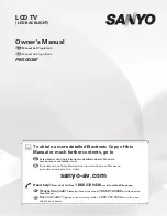
Summary of Contents for L32HDTV10A

Page 1: ...Service Manual V Inc 320A Kalmus Drive Costa Mesa CA 92626 TEL 714 668 0588 FAX 714 668 9099 Top Confidential Model VIZIO L32HDTV10A ...

Page 2: ...4 Factory Preset Timings 4 1 5 Pin Assignment 5 1 6 Main Board I O Connections 6 1 7 Theory of Circuit Operation 7 1 8 Waveforms 8 1 9 Trouble Shooting 9 1 10 Block Diagram 10 1 11 Spare parts list 11 1 12 Complete Parts List 12 1 Appendix 1 Main Board Circuit Diagram 2 Main Board PCB Layout 3 Assembly Explosion Drawing Block Diagram ...

Page 3: ...io communications However there is no guarantee that the interference will not occur in a particular installation If this equipment does cause unacceptable interference to radio or television reception which can be determined by turning the equipment off and on the user is encouraged to try to correct the interference by one or more of the following measures reorient or relocate the receiving ante...

Page 4: ...uto adjust function for automatic adjument of screen display 6 Smoothing function enables display of smooth texts and graphics even if image withresolution lower than 1366x768 is magnified 7 Picture In Picture PIP funtion to show TV or VCR images 8 Power saving to reduce consumption power too less than 3W 9 On Screen Display user can define display mode i e color brightness contrast sharpness soun...

Page 5: ...nt Hard coating 3H Anti glare treatment of the front polarizer Color Depth 8 bit 16 7 M colors Viewing Angle CR 10 Viewing angle free R L 176 Typ U D 176 Typ Power Consumption Total 125Watt Typ Logic 4 5W Lamp 120W IBL 6 0mA 2 OPTICAL CHARACTERISTICS Viewing Angle by Contrast Ratio Left 88 typ Right 88 typ Top 88 typ Bottom 88 typ 3 SIGNAL Refer to the Timing Chart 3 1 Input Voltage Level 90 240 V...

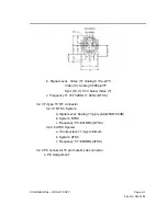
Page 6: ...w Video Y c Frequency H 15 734KHz V 60Hz NTSC 3 2 3 F Type TV RF connector 3 2 3 1 NTSC System a Signal Level Analog 1Vp p typical 45dB 90dB b System NTSC c Frequency 55 801MHz NTSC 3 2 3 2 ATSC System a IF output level 1Vp p minimum b System ATSC c Frequency 57 863MHz ATSC 3 2 4 PC connector 15 pin male D sub connector a Pin Assignment ...

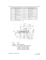
Page 7: ...ideo R G B Analog 0 7Vp p 75 Sync H V TTL level c Sync Type TTL Separate Composite or Sync On Green d Sync polarity Positive or Negative e Frequency H support to 30K 70KHz V support to 50 85Hz Pixel Clock support to 110MHz 3 2 5 HDMI Signal Digital HD a Pin Assignment ...

Page 8: ...DENTIAL DO NOT COPY Page 2 4 File No SG 0182 b Type TYPE A c Polarity Positive or Negative d Frequency H 15 734KHz V 60Hz NTSC 480i H 31KHz V 60Hz NTSC 480p H 45KHz V 60Hz NTSC 720p H 33KHz V 60Hz NTSC 1080i ...

Page 9: ...Hz V 60Hz NTSC 720p H 33KHz V 60Hz NTSC 1080i b Signal level Y 1Vp p Pb 0 350Vp p Pr 0 350Vp p c Impedance 75 3 2 7 Audio Signal a Signal Level 1Vrms b Frequency Response 250Hz 20KHz 4 Input Connectors RJ11 D SUB15PIN mini jack PC Audio in HDMI CONNECT RCAX2 component RCAX3 AUDIO in RCAX3 composite RCAX3 AUDIO in F CONNECTx2 S Video 5 POWER SUPPLY Power Consumption 220W MAX Power OFF to less than ...

Page 10: ...and chlorine type materials for the cover case are not desirable because the former generates corrosive gas of attacking the polarizer at high temperature and the latter causes circuit break by electro chemical reaction 6 Do not touch push or rub the exposed polarizes with glass tweezers or anything harder than HB pencil lead And please do not rub with dust clothes with chemical treatment Do not t...

Page 11: ...high frequency circuits Sufficient suppression to the electromagnetic interference shall be done by system manufacturers Grounding and shielding methods may be important to minimized the interference 9 3 HANDLING PRECAUTIONS FOR PROTECTION 1 The protection film is attached to the bezel with a small masking tape When the protection film is peeled off static electricity is generated between the film...

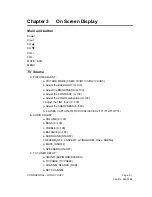
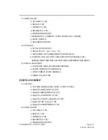
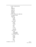
Page 12: ...GHTNESS 0 100 d Adjust the CONTRAST 0 100 e Adjust the COLOR saturation 0 100 f Adjust the TINT hue 0 100 g Adjust the SHARPNESS 0 100 h CLOSED CAPTION OFF CC1 CC2 CC3 CC4 TT1 TT2 TT3 TT4 B AUDIO ADJUST a VOLUME 0 100 b BASS 0 100 c TREBLE 0 100 d BALANCE 0 100 e SURROUND ON OFF f REVERB OFF CONCERT LIVINGROOM HALL ARENA g MUTE ON OFF h SPEAKERS ON OFF C TV TUNER SETUP a SOUND SAP MONO STEREO b TV...

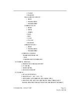
Page 13: ... LEFT MIDDLE RIGHT BOTTOM LEFT BOTTOM CENTER BOTTOM RIGHT F SPECIAL FEATURES a LANGUAGE ENGLISH FRANCE SPANISH b SLEEP TIMER OFF 30 60 90 120 c WIDE FORMAT NORMAL WIDE ZOOM PANORAMIC d RESET ALL SETTING PC Analog Mode A PICTURE ADJUST a AUTO PICTURE Run b Adjust the BACKLIGHT 0 100 c Adjust the BRIGHTNESS 0 100 d Adjust the CONTRAST 0 100 e Adjust the V POSITION 0 100 f Adjust the H SIZE 0 100 g A...

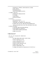
Page 14: ...TOP RIGHT MIDDLE LEFT MIDDLE RIGHT BOTTOM LEFT BOTTOM CENTER BOTTOM RIGHT E SPECIAL FEATURES a LANGUAGE ENGLISH FRANCE SPANISH b SLEEP TIMER OFF 30 60 90 120 c WIDE FORMAT WIDE NORMAL d RESET ALL SETTING DIGITAL HD MODE A PICTURE a PICTURE MODE USER VIVID1 VIVID2 VIVID3 b Adjust the BACKLIGHT 0 100 c Adjust the BRIGHTNESS 0 100 d Adjust the CONTRAST 0 100 e Adjust the COLOR saturation 0 100 f Adju...

Page 15: ...LEFT TOP CENTER TOP RIGHT MIDDLE LEFT MIDDLE RIGHT BOTTOM LEFT BOTTOM CENTER BOTTOM RIGHT E SPECIAL FEATURES a LANGUAGE ENGLISH FRANCE SPANISH b SLEEP TIMER OFF 30 60 90 120 c WIDE FORMAT NORMAL WIDE ZOOM d RESET ALL SETTING Video Sources AV1 AV2 AV3 ANALOG HD1 ANALOG HD2 A PICTURE a PICTURE MODE USER VIVID1 VIVID2 VIVID3 b Adjust the BACKLIGHT 0 100 c Adjust the BRIGHTNESS 0 100 d Adjust the CONT...

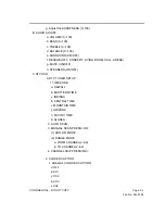
Page 16: ...RCE AV2 AV3 ANALOGHD1 ANALOG HD2 DIGITAL HD RGB TV c SIZE SMALL 20 MEDIUM 30 LARGE 40 d POSITION TOP LEFT TOP CENTER TOP RIGHT MIDDLE LEFT MIDDLE RIGHT BOTTOM LEFT BOTTOM CENTER BOTTOM RIGHT E SPECIAL FEATURES a LANGUAGE ENGLISH FRANCE SPANISH b SLEEP TIMER OFF 30 60 90 120 c WIDE FORMAT NORMAL WIDE ZOOM PANORAMIC d RESET ALL SETTING DTV Sources A PICTURE a PICTURE MODE USER VIVID1 VIVID2 VIVID3 b...

Page 17: ...T LIVING ROOM HALL ARENA g MUTE ON OFF h SPEAKERS ON OFF C DTV OSD a DTV TUNER SETUP 1 TIME ZONE α HAWALL β EASTTERN TIME γ INDIANA δ CENTRAL TIME ε MOUNTAIN TIME ζ ARIZONA η PACIFIC TIME θ ALASKA 2 AUTO SCAN 3 MANUAL SCAN PRESS OK 1 ADD ON MODE 2 RANGE MODE α FORM CHANNEL 2 69 β TO CHANNEL 2 69 4 CHANNEL SKIP PRESS OK b CLOSED CAPTION 1 ANALOG COLOSED CAPTION α OFF β CC1 γ CC2 δ CC3 ε CC4 ...

Page 18: ...E3 ε SERVICE4 ζ SERVICE5 η SERVICE6 3 DIGITAL CAPTION STYLE PRESS OK 1 AS BROADCASTER 2 CUSTOM FONT SIZE α LARGE β SMALL γ MEDIUM FONT COLOR α BLACK β WHITE γ GREEN δ BLUE ε RED ζ CYAN η YELLOW θ MAGENTA FONT OPACITY α SOLID β TRANSLUCENT γ TRANSPARENT BLACKGROUND COLOR α BLACK β WHITE γ GREEN δ BLUE ε RED ζ CYAN ...

Page 19: ...DOW OPACITY α SOLID β TRANSLUCENT γ TRANSPARENT c PARENTAL CONTROL PASSWORD PRESS OK 1 0000 2 CHANNEL BLOCK PRESS OK D PARENTAL CONTROL a PARENT LOCK ENABLE ON OFF b TV RATING c MOVIE RATING d ACCESS CODE EDIT E PIP SETUP a STYLE OFF PIP POP b SOURCE AV1 AV2 AV3 TV c SIZE SMALL 20 MEDIUM 30 LARGE 40 d POSITION TOP LEFT TOP CENTER TOP RIGHT MIDDLE LEFT MIDDLE RIGHT BOTTOM LEFT BOTTOM CENTER BOTTOM ...

Page 20: ...CONFIDENTIAL DO NOT COPY Page 3 9 File No SG 0182 F SPECIAL FEATURES a LANGUAGE ENGLISH FRANCE SPANISH b SLEEP TIMER OFF 30 60 90 120 c WIDE FORMAT NORMAL WIDE d RESET ALL SETTING ...

Page 21: ...4 3 3V working ok LED is lighting It is in power saving 1 Check video cable 2 Is the timing supported 3 Check sync input 4 Check VGASOG rout if analog SOG Is backlight on 1 Check J1 PIN 1 2 Is inverter ok U9 no data out It means data to LVDS 1 Is J6 connecting well 2 Check J1 5V 12V 3 Is panel ok U9 no data in 1 Is U9 working good 2 Is U11 U12 working good 3 IS U10 working good 1 Check P3 D sub In...

Page 22: ...U20 input correct 1 Check P2 signal 2 Check signal between P2 and U20 IF AV1 AV2 mode 3 Check Tuner U20 IF TV mode 4 Check J4 J6 IF AV3 S Video 5 Check U20 POWER 9V 6 Check U22 data input output LVDS output correct 1 Check signal between U20 and U9 1 Chcak J6 Connect is good 2 Is panel working ok END U20 output correct 1 Check signal between U20 and U9 2 Check U9 clock 27MHz 3 Check U9 power ...

Page 23: ...CTLY Start Input signal good 1 Check video 2 Check host s setting U21 input correct 1 Check signal between P8 U21 2 Check U21 power 3 3V U9 input correct 1 Check signal between U21 U9 2 Check U9 Clock 27MHZ LVDS output correct 1 Check U9 2 Check U9 power 3 3V 1 8V 1 Is J6 connected good 2 Is panel working ok END ...

Page 24: ...SPLAY CORRECTLY Input signal good Start 1 Check video 2 Check host s setting U16 input correct 1 Check p1 connect 2 Check signal between P1 and U16 U16 no data out 1 Check U16 power 2 Check between signal U16 and U9 3 Check clock 28 224MHZ 1 Is J6 connected good 2 Is panel working ok END ...

Page 25: ...Check power cable connection J1 U7 pin 5 6 7 8 The voltage is about 5V while power switch on 1 J1 connection good 2 Check U9 GPIO Pin U4 pin2 The voltage is about 3 3V 1 J1 to connection good 2 Check U4 U6 pin 3 The voltage is about 9V 1 Check U9 GPIO Pin 2 Check U6 U5 pin2 The voltage is about 1 8V 1 Check J1 Connect 2 Check U5 L5 U14 pin2 The voltage is about 2 5V while power switch on 1 Check U...

Page 26: ...0 TROUBLE OF DDC READING Start Analog DDC OK Support DDC1 2B 1 Analog cable ok 2 Check signal U18 to P3 3 Check U18 Voltage 4 Is compliant protocol HDMIDDC OK Support DDC1 2B 1 Analog cable ok 2 Check signal U17 to P1 3 Check U17 Voltage 4 Is compliant protocol END ...

Page 27: ...CONFIDENTIAL DO NOT COPY Page 10 7 File No SG 0182 TROUBLE OF THE DTV ...

Page 28: ......

Page 29: ......

Page 30: ......

Page 31: ......

Page 32: ......

Page 33: ......

Page 34: ......

Page 35: ......

Page 36: ......

Reviews: