background image

EN - 9

English

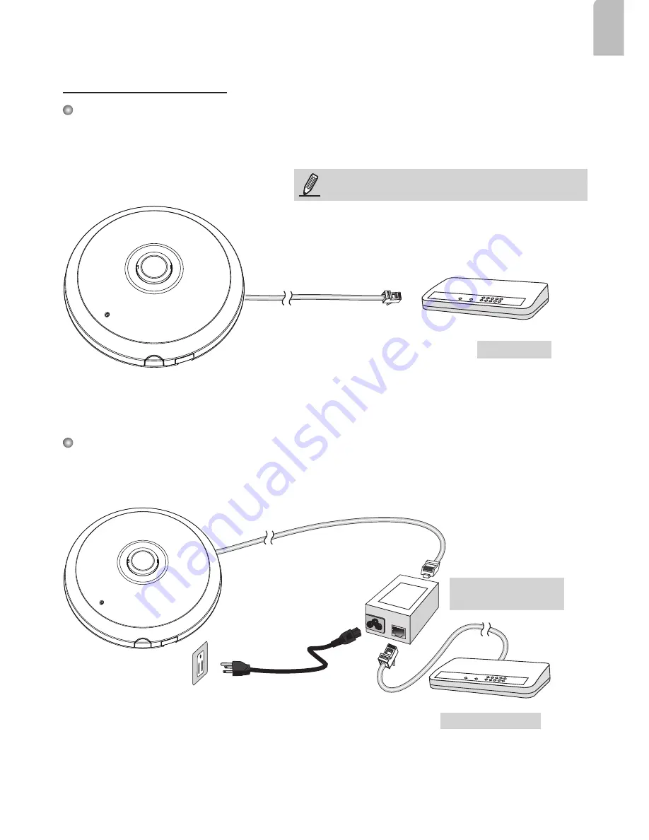
 When using a non-PoE switch

Use a PoE power injector (optional) to connect between the Network Camera and a non-PoE 

switch.

Power over Ethernet (PoE)

 When using a PoE-enabled switch

The Network Camera is PoE-compliant, allowing transmission of power and data via a single 

Ethernet cable. Follow the below illustration to connect the Network Camera to a PoE-enabled switch 

via Ethernet cable.

POWER

COLLISION

LINK

RECEIVE

PARTITION

1

2

3

4

5

PoE Switch

POWER

COLLISION

LINK

RECEIVE

PARTITION

1

2

3

4

5

PoE Power Injector 

(optional)

Non-PoE Switch

NOTE:

1. This equipment is only to be connected to PoE 

networks without routing to outside plants.

2. For PoE input connection, use only UL listed I.T.E.  

with PoE output.

Summary of Contents for SF8172

Page 1: ...g temperature Do not place the Network Camera on unsteady surfaces Do not touch the Network Camera during a lightning storm Do not insert sharp or tiny objects into the Network Camera Do not drop the...

Page 2: ...over IMPORTANT Record the MAC address under the camera base before installing the camera Inner View Header J7 Spring Contacts A Lens Contacts for Internal Microphone B Header J6 Ethernet 10 100 RJ45 S...

Page 3: ...y Then follow the steps below to install the camera to either a ceiling or a wall If you plan to route cables from the side of camera remove the rubber slide cover from the dome cover Slide cover Conn...

Page 4: ...cal mounting tab located on the edge of the cabling cutout 3 Make a clearance between cables and the vertical mounting tab Arrange the cables neatly to avoid getting in the way when the dome cover is...

Page 5: ...bles through the pendant pipe and the pendant head IMPORTANT Refer to the Panoramic PTZ Installation Guide in your product CD for design considerations before you proceed with physical installation B...

Page 6: ...white header connectors to the J6 and J7 connectors 4 Connect the Ethernet cable to the RJ 45 socket 5 You will find a desiccant bag attached to the camera Replace the desiccant bag included in the ca...

Page 7: ...t bracket to mark the positions where holes will be drilled to secure the bracket and routing cables Note that screws are user supplied and they should be at least 11mm long 2 Feed cables through the...

Page 8: ...tion without PoE 1 Connect RJ45 Ethernet cable to a switch 2 Connect the power cable from the Network Camera to a power outlet 3 If you have external devices such as sensors and alarms make the connec...

Page 9: ...ta via a single Ethernet cable Follow the below illustration to connect the Network Camera to a PoE enabled switch via Ethernet cable POWE R COLLIS ION LINK R E C E IVE PAR TITION 1 2 3 4 5 PoE Switch...

Page 10: ...l pop up Double click on the MAC address that matches the one printed on the camera label or the serial number on the package box label to open a browser management session with the Network Camera 5 1...

Reviews: