background image


VIVOTEK - A Leading Provider of Multimedia Communication Solutions


36 - User's Manual


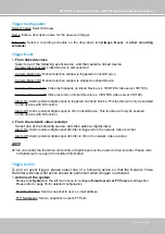
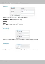
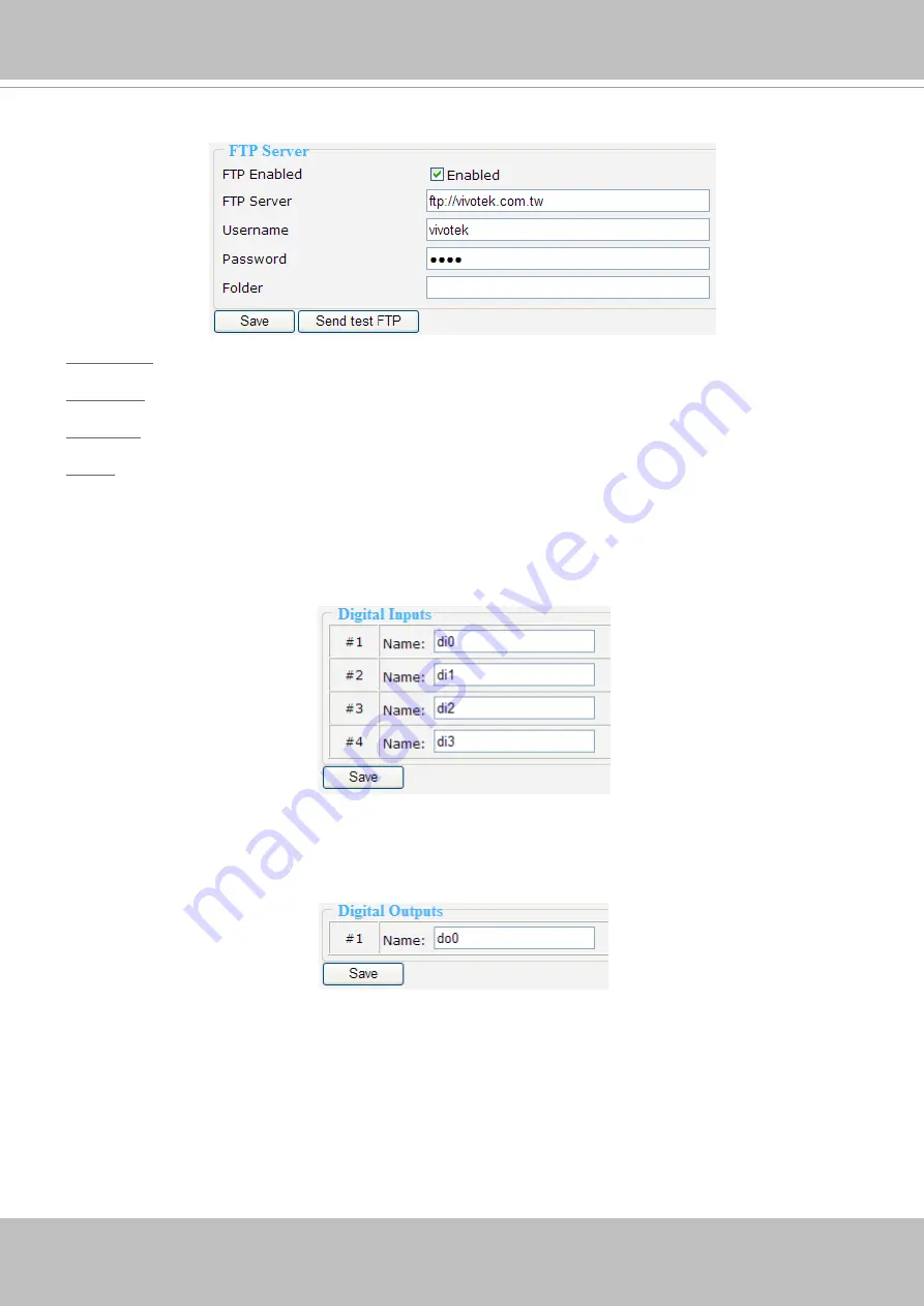
FTP Server

FTP Server: Enter the domain name or IP address of the FTP server�

Username: Enter the login name of the FTP account�

Password: Enter the password of the FTP account�

Folder

: Enter a folder to place the media file.

Check 

Enabled

 and click 

Save

 to enable the settings�

Digital Input

Here you can modify the Name of external digital inputs on the network video recorder�

Digital Output

Here you can modify the Name of external digital output on the network video recorder�

Summary of Contents for NR7401

Page 1: ......

Page 2: ...lation 7 Network deployment 8 Home Page 16 Configuration 18 Device 18 Network 20 LAN 20 Access list 21 DDNS 22 Security 24 Schedule 26 Recording Policy 28 Trigger 31 System 34 Maintenance 36 Backup 37 System log 38 Monitor 39 User Interface of Monitor Page 39 Functions of Monitor Page 41 History 44 User Interface of History Page 44 Functions of History Page 45 Appendix 50 Technical Specifications ...

Page 3: ...ndwidth is minimized NR7401 also has four digital input and one digital out interfaces to allow for connection with external sensors and alarms In addition NR7401 offers an USB port which can be used to connect with external storage devices for video backup Read before use The use of surveillance devices may be prohibited by law in your country It is the user s responsibility to ensure that the op...

Page 4: ... 1 2 3 4 5 6 7 8 9101112 1 Power 2 Relay output COM 3 Relay output N O 4 Digital Input 1 5 Digital Input 1 Ground 6 Digital Input 2 7 Digital Input 2 Ground 8 Digital Input 3 9 Digital Input 3 Ground 10 Digital Input 4 11 Digital Input 4 Ground 12 Ground Power POE Status HDD WAN LAN1 LAN2 LAN3 LAN4 USB socket Status indicator NR7401 Network Video Recorder RESET LAN4 LAN3 LAN2 LAN1 WAN 1 2 3 4 5 6 ...

Page 5: ...VIVOTEK A Leading Provider of Multimedia Communication Solutions User s Manual 5 DI DO Diagram Refer to the following illustration for connection method ...

Page 6: ...ion Off No connection Blink Activity on LAN port 2 LAN3 On With connection Off No connection Blink Activity on LAN port 3 LAN4 On With connection Off No connection Blink Activity on LAN port 4 Hardware System Requirement Computer Microsoft Windows XP Professional SP2 or above Internet Explorer 6 0 or later Hard disk SATA hard drive for up to 1TB Hardware Reset There is a indented reset button on t...

Page 7: ...d Disk installation Before using the Network Video Recorder the first step is to install a SATA hard disk for re corded video Please follow the steps below 1 Make sure the power is off 2 Use a screwdriver to loose five screws and then slide to remove the upper cover 3 Loose the screw and take out the hard disk bracket 4 Put your hard disk into the bracket and secure it with the supplied four screw...

Page 8: ...our want to access NR7401 over the Internet connect NR7401 to the Internet via WAN socket 4 If you have external devices such as sensors and alarms make connections from general I O terminal block RESET LAN4 LAN3 LAN2 LAN1 WAN 1 2 3 4 5 6 7 8 9101112 Activity Pow er M IC Internet WAN LAN LAN LAN 1 2 Network Camera PoE Network Camera without PoE 3 4 Cable DSL Modem or router 1 Power 2 Relay output ...

Page 9: ...o link your computer to NR7401 for the first time 1 Connect your computer to NR7401 LAN port using an Ethernet cable 2 Setup your computer in DHCP mode a Click Start My Network Places View network connections b Right click Local Area Connection and then click Properties c Select Internet Protocol TCP IP and then click Properties ...

Page 10: ... Solutions 10 User s Manual d Select Obtain an IP address automatically and Obtain DNS server address automatically as below Then click OK to enable your settings 3 Then NR7401 will server as a router and automatically assign an IP address to your computer ...

Page 11: ... page 9 to setup your computer in DHCP mode and then directly enter the default IP address for NR7401 http 192 168 100 1 in the addrees bar of the web browser The webpage of the Network Video Recorder will be displayed for you to configure the settings LAN Settings Configuration Go to Configuration LAN to verify the settings as below http 192 168 100 1 ...

Page 12: ...llow the steps below to verify the settings 1 Go to Configuration Network Click LAN Get IP address automatically 2 Click Apply to enable the settings 3 If your computer is in the same domain with the WAN IP address then you can use VIVOTEK Installation Wizard 2 IW2 to search for the Network Video Recorder easily Please follow the steps below to run IW2 a Install the IW2 under the Software Utility ...

Page 13: ...o Recorder Internet connection with static IP Choose this connection type if you want to use a static IP for the Network Video Recorder Please follow the steps below to change the settings 1 Go to Configuration Network Click LAN Use fixed IP address 2 Enter the static IP Subnet Mask Default Router Primary DNS Server provided by your ISP 3 Click Save to enable the settings 0002D171893F 00 02 D1 07 ...

Page 14: ... type if you are connected to the Internet via a DSL Line Please follow the steps below to change the settings 1 Go to Configuration Network Click PPPoE 2 Enter the User Name and Password provided by your ISP 3 Click Save to enable the settings 4 The IP Address Subnet Mask Default Router Primary DNS Server will automatically show up in the above blanks 1 2 3 4 5 ...

Page 15: ... you receive a message saying that your Internet Explorer security settings prohibit installing Active X components please enable your Active X Controls for your browser 1 Click Tools Internet Options Security Custom level on the tool bar of the Internet browser 2 Look for Download signed ActiveX controls select Enable or Prompt Click OK 3 Refresh your web browser and then install the Active X Fol...

Page 16: ...page is for you to search and playback recorded data in a specific range of time Configuration Click this button to open the Configuration page This page is for you to configure the settings of the network video recorder It is suggested that a password is applied to the Network Video Recorder so that only the authorized user can configure the settings Please refer to page 18 for detailed informati...

Page 17: ...panel NOTE The Username will be blank if you have not setup a password in the Security page Please refer to page 25 for detailed information Depending on user s privilege of the user account the access to the configutation page may be restricted For more information about user s privilege please refer to Manage Privilege on page 26 User Name default root Login Time yyyy mm dd hh mm ss Current Time...

Page 18: ...ill be explained in the following sections Device This page allows user to add a new device or modify an inserted device NR7401 supports simultaneous 9 CH video recording Following is the current support list of NR7401 7000 series 6000 series IP7135 7137 IP6112 6122 IP7131 7132 IP6117 6127 IP7138 7139 PZ6112 6122 IP7142 PZ6114 6124 IP7151 7152 FD6111V 6121V IZ7151 FD6112V 6122V PT7135 7137 SD6112V...

Page 19: ... click Stop Searching if the linked devices are all displayed on the list 3 Select a device to be inserted Modify the Device Name if necessary 4 Click Add Device to enable the settings You can also manually install a new device in LAN Please follow the steps below 1 Select Add new on the drop down list 2 Enter the Device Name 3 Enter the Username Password if the device needs to do authentication 4...

Page 20: ...ly by the NR7401 server 7 Enter the HTTP Port for the device 8 Click Save to enable the settings NOTE If you want to modify the settings of the device select it on the drop down list The device information will be displayed in the following blanks then you can modify the settings of the device By default the recording schedule is Always continuous recording If you want to modify the recording sche...

Page 21: ...fault Subnet Mask is 255 255 255 0 If you set up the network video recorder in LAN and link its LAN Port to network cameras and computer as the picture shows below the DHCP server of network video recorder will automatically assign IP address to those linked devices 192 168 100 2 192 168 100 254 NOTE The starting and ending address of the DHCP server must be in the same subnet as the IP address of...

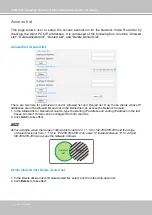
Page 22: ...d list and not in the Denied list can access the Network Camera 1 In the Allowed list or Denied list column type the starting IP address and ending IP address in the text boxes A total of 10 lists can be configured for both columns 2 Click Add to take effect NOTE For example when the range of allowed list is set from 1 1 1 0 to 192 255 255 255 and the range of denied list is set from 1 1 1 0 to 17...

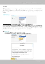
Page 23: ... DDNS Service Select a DDNS provider from the Provider drop down list VIVOTEK offers Safe100 net a free dynamic domain name service to VIVOTEK customers It is recommended that you register with the Safe100 net to access the Network Video Recorder from the Internet Additionally we offer other DDNS providers such as Dyndns org DHS org TZO com dyn interfree it Note that to utilize this feature please...

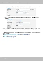
Page 24: ...ngs window enter your account information and then click Save to enable the settings Forget key Click this button if you forget the key of Safe100 net Your account information will be sent to your e mail address Please refer to the following links to apply a dynamic domain account when selecting other DDNS providers Dyndns org Dynamic Dyndns org Custom visit http www dyndns com TZO com visit http ...

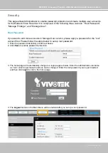
Page 25: ...unts in Manage User column please apply a password for the root account first Please follow the steps below to set up root password 1 Enter the password identically in both text boxes 2 Click Save to enable password protection 3 The home page will automatically change to a login page as below Enter the administrator username as root which is permanent and can not be changed Enter the root password...

Page 26: ...O Playback Control History page O O O NOTE The user privileges of an administrator are always enabled and cannot be changed Operator and Viewer doesn t heve the permission to access the Configuration page Manage User Administrator can add up to twenty user accounts 1 Enter the new user s name and password 2 Select the Privilege for new user account Click Save to take effect Here you also can chang...

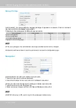
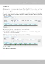
Page 27: ...ault recording schedule always Therefore once you insert a device to the network video recorder it will begin to record live video continuously Please follow the steps below to add a new recording schedule 1 Enter a descriptive name for the new schedule 2 Select a day and enter a time frame in the format of 24hr 3 Click Add to take effect The new recording schedule will show up in the Schedule Dis...

Page 28: ...ur recording schedule The new recording schedule will also show up on the Trigger Configuration as below Click Trigger on the left Menu Then you can select Always Never or schedule1 as your schedule for event trigger If you want to delete a recording schedule select it on the drop down list Select Schedule and then click Remove to delete it If you want to delete a time frame select it on the drop ...

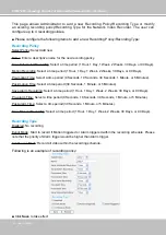
Page 29: ... insert a device to the network video recorder it will begin to record live video continuously but only save 1 hour recorded video clips The recorded video will be displayed on the History page For example The user added a VIVOTEK FD7132 to NR7401 Following pictures shows the default settings Configuration Device Configuration Recording Policy Recorded video clips on History page only 1 hour video...

Page 30: ... Days Pre motion Time Select a time period 0 Seconds 10 Seconds 30 Seconds 1 Minute or 5 Minutes Post motion Time Select a time period 30 Seconds 1 Minute or 5 Minutes Save Alarm Recording Select a time period 1 Hour 1 Day 1 Week 2 Weeks 30 Days or 90 Days Pre alarm Time Select a time period 0 Seconds 10 Seconds 30 Seconds 1 Minute or 5 Minutes Post alarm Time Select a time period 30 Seconds 1 Min...

Page 31: ...l 31 The new recording policy will show up on the device information as below Click Device on the left Menu Then you can select Default or policy1 as your recording policy If you want to delete a recording policy select it on the drop down list and then click Remove to delete it ...

Page 32: ...lustration an event can be triggered by many sources such as motion detection or external alarm digital input devices When an event is triggered you can specify what kind of action should be performed You can assign the Network Video Recorder to send snapshots jpg or txt document to your e mail address or FTP site Please configure the following items to please follow the steps below to add a new e...

Page 33: ...d on the devices with DI function Alarm Off Alarm external digital input is off on linked Device This function will only be enabled on the devices with DI function 2 From the network video recorder Select one of the following source and then select a digital input Alarm On Alarm external digital input di0 di4 is triggered on the network video recorder Alarm Off Alarm external digital input di0 di4...

Page 34: ...l Input on page 36 for detailed information E mail FTP notification 1 E mail format Event Type Camera disconnected Motion on Motion off Alarm on Alarm off Title Camera disconnected Motion on Motion off Alarm on Alarm off Content Camera Y is disconnected Motion X triggered on Camera Y Motion X stopped on Camera Y Alarm trigger on Camera Y Alarm off on Camera Y With Snapshot jpg No Yes Yes Yes Yes 2...

Page 35: ... when the power of the system is turned off Sync with computer time Select this option to synchronize the date and time of the Network Video Recorder with the local computer The read only date and time of the PC is displayed as updated Manual The administrator can enter the date and time manually Note that the date and time format are yyyy mm dd and hh mm ss Automatic The Network Time Protocol is ...

Page 36: ...e login name of the FTP account Password Enter the password of the FTP account Folder Enter a folder to place the media file Check Enabled and click Save to enable the settings Digital Input Here you can modify the Name of external digital inputs on the network video recorder Digital Output Here you can modify the Name of external digital output on the network video recorder ...

Page 37: ...ecorder to factory default Please note that the linked devices will be removed from the Device setting page and all settings will be erased But the recorded data will remain on the History page The following message is displayed during the rebooting and restoring process Hard Disks This column shows the information of your hard disk For the first time you install the hard disk please format it bef...

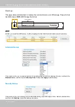
Page 38: ...information column as below Scheduled Backup This column is for you to select what kind of recording data you want to backup Check or uncheck the Enabled blanks and then select a Backup Time Finally click Apply to start backup Manually Backup This column is for you to backup all recorded data during a specific range of time Select a desired time and then click Backup to start the backup procedure ...

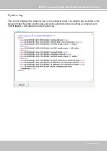
Page 39: ...s User s Manual 39 System log This column displays the system s log in chronological order The system log is stored in the Network Video Recorder s buffer area and will be overwritten when reaching a certain amount Click Refresh it will update the latest system log ...

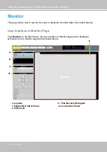
Page 40: ...e view or playback recorded video from linked devices User Interface of Monitor Page Click Monitor on the Main Menu the user interface of Monitor page will be displayed Following is the Monitor page without linked device a b c d e a Layouts b Time Bar and Histogram c Digital I O Control Panel d Live Control Panel e Video Cell ...

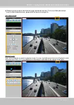
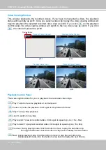
Page 41: ...ked devices For more information about how to insert linked devices please refer to Device on page 18 Live viewing mode Playback mode Click on the Histogram to switch to playback mode The Live Control Panel will turns into Playback Control Panel as below Click on the Playback Control Panel it will switch to live viewing mode again ...

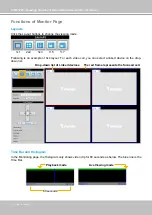
Page 42: ... 3x3 1 5 1 7 Following is an example of 4x4 layout For each video cell you can select a linked device on the drop down list Time Bar and Histogram In the Monitoring page the Histogram only shows video clip for 80 seconds as below The blue line is the Time Bar Drop down list of Linked devices The red frame represents the focused cell 80 seconds Playback mode Live Viewing mode ...

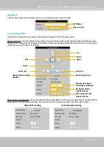
Page 43: ... refer to page 29 for detailed information Following example shows that the current recording type of the focused cell is Alarm recording Manual Recording Button If you click Manual Recording Button on the Live Control Panel the Recording Type will turn into Manual recording If you want to stop manual recording click the button again up home right left down zoom in zoom out Recording Type Manual R...

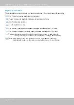
Page 44: ... stop video playback Live To switch to live video Play rewind To rewind recorded video Click again to speed up 4x 16x 64x Play forward To playback recorded video Click again to speed up 4x 16x 64x Previous During playing mode click this button to move to play the last video clip During paused mode click this button to step back to display the last I frame Next During playing mode click this button...

Page 45: ...ace to playback recorded video and browse the live view from linked devices User Interface of History Page Click History on the Main Menu the user interface of History page will be displayed as below d a a Time Picker b Time Bar and Histogram c Recorded Video Clips d Video Viewing Window e Playback Control Panel f Recording Type e b c f ...

Page 46: ...button to go the last period of time last Hour Day Week or Month Click this button to go the next period of time next Hour Day Week or Month Manually input the time and then click this button to go the selected period of time selected Hour Day Week or Month Time Bar and Histogram Recorded Video Clips The recorded video clips in the selected period of time will show up on the histogram and be liste...

Page 47: ...t an AVI file of a video clip to your local computer select it and then click this button Click this button to refresh the latest video clip Recording Type The following color bar will show up on the histogram according to the recording type Grey bar Empty No recorded video Green bar Cache Temporary recording data prepare for pre post motion or pre post alarm recording Yellow bar Scheduled Record ...

Page 48: ...ns 48 User s Manual Example Following video clips list contains different kinds of recording type NOTE For the length of Scheduled Recording Motion Recording Alarm Recording and Manual Recording please refer to Recording Type on page 30 for detailed configuration ...

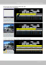
Page 49: ...ovider of Multimedia Communication Solutions User s Manual 49 There are two ways to playback recorded video clips 1 Click a desired time on the histogram 2 Click on a video clip and then click on the playback control panel ...

Page 50: ...orded video clips Play To start or resume playback at normal speed Pause To pause the playback Click again to step forward a frame Stop To stop video playback Live To switch to live video Play rewind To rewind recorded video Click again to speed up 4x 16x 64x Play forward To playback recorded video Click again to speed up 4x 16x 64x Previous During playing mode click this button to move to play th...

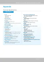
Page 51: ...tion Max 21W without PoE camera Max 35W with 4 PoE cameras 802 3af compliant Power over Ethernet Approvals CE FCC C Tick VCCI UL CB Operating Environments Temperature 0 50 C 32 122 F Humidity 20 80 RH Viewing System Requirements OS Microsoft Windows 2000 XP Vista Browser Internet Explorer 6 x or above Installation Management and Maintenance Installation Wizard 2 Supports firmware upgrade System CP...

Reviews: