background image

Tighten the screws

Connect power cable and other signal 
cable to projector

To 

Install


The


Projector


On


The


Projector


Wall


Mount

A

B

Screen Adjustment Direction

B

A

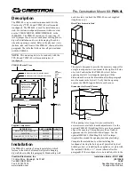
Note: To make adjustments to meet your demands, screws must be loosened in a specific 
order. (When the length of the inside arm does not meet your requirements, then you should 
loosen the screws on the outside arm to adjust the middle arm. Under this  circumstance, the 
number read on the middle arm  is correct).

To Adjust The Projector Forwards/Backwards

Pg.6

Power cable 
and signal cable

290mm

260mm

200mm

13in

12in

11in

10in

9in

8in

230mm

320mm

360mm

14in

15in

390mm

420mm

16in

17in

290mm

13in

12in

320mm

360mm

14in

420mm

16in

17in

D

B

A

Check the scaleplate 
to see the distance from 
mounting plate 

to


the


wall

.

Summary of Contents for LT30C-F

Page 1: ...Model LT30C F ...

Page 2: ...Φ10mm Anchor bolt L5 Allen key 4 Screw M4X10 diagrammatic presentation designation quantity 1 L3 Allen key Screw M6X15 Wall Plate Cover X 1 2 3 4 5 7 8 9 Pg 2 G M4 connecting screw 4 Projection screen V Offset Wall plate Projection screen Bottom of mounting plate Top of image V Offset Wall plate must be aligned to center of screen L1 L2 Wall Cover X 1 ...

Page 3: ...3x 202 inch cm 101 05 256 7 120 9 307 1 136 78 347 4 156 62 397 8 From a projecting surface to the rear of the unit L2 Projection image size Installation distance 20 15 51 2 73 67 187 1 116 49 295 9 169 99 431 8 173 69 441 2 227 22 577 1 270 03 685 9 323 53 821 8 WXGA 1280 x 800 From a projecting surface to the rear of the unit L1 cm x cm 80 105 Diagonal Width x Height inch 65 125 132 x 99 163 x 1...

Page 4: ...ncrete wall installation ood stud wall and gypsum board thickness not W must be a minimum 20x12 inch Stud thickness must be a minimum 3 greater than 3 8 inch If the wall is not strong enough reinforce it sufficiently before installation Please contact if you have any questions about mounting surface issue manufacturer All of the fastening screws provided have to be used Calcium silicate board mount...

Page 5: ...to your need Tighten the screw F after locating the projector position C F Move the projector mounting plate leftwards rightwards to determine the projector position Pg 5 Sliding distance of adjusting the projector upward downward 3 15 80mm A B Leftward Rightward sliding distance E G If the surface is not at pls use the G to avoid interference ...

Page 6: ... does not meet your requirements then you should loosen the screws on the outside arm to adjust the middle arm Under this circumstance the number read on the middle arm is correct To Adjust The Projector Forwards Backwards Pg 6 Power cable and signal cable 290 mm 260 mm 200 mm 13in 12in 11in 10in 9in 8in 230 mm 320 mm 360 mm 14in 15in 390 mm 420 mm 16in 17in 290mm 13in 12in 320mm 360mm 14in 420mm ...

Page 7: ...t Direction A Screen Adjustment Direction B A B A B Screen Adjustment Direction To Adjust The Vertical Tilt Knob To Adjust The Projector Upwards Downwards To Adjust The Horizontal Roll Knob Adjustment Knob Adjustment Knob Pg 7 C F ...

Page 8: ...41L3603 EN MC LT30C F 11 46 lbs 5 2kg Product Weight 12 8 325mm 29 1 740mm ...

Reviews: