46
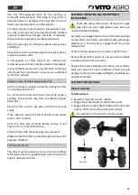
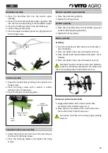
Adjustable plough assembly
1.
Remove the ring bolt from the fixed bracket attached
to the gearbox;
2.
Attach the adjustable plough on the fixed bracket;
3.
Insert the ring bolt and the beta key;
4.
Adjust the horizontal fixing angle on the adjusting
screws;
5.
Place the
adjustable plough’s
depth regulator into
the holder;
6.
Place the
fixing pin into one of the depth regulator’s
holes according to the desired height. Insert the beta
key.
7.
Adjust the trench width using the adjusting bolts
placed in the adjustable plough;
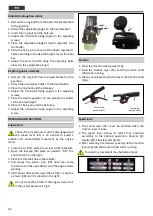
Depth regulator assembly
1.
Remove the ring bolt from the fixed bracket on the
gearbox;
2.
Attach the accessories holder to the fixed holder;
3.
Place the ring bolt and the beta key;
4.
Adjust the horizontal fixing angle on the adjusting
screws;
5.
Place the depth regulator on the accessory’s holder
at the desired height;
6.
Place the fixing pin and the beta key;
7.
Adjust the horizontal fixing angle on the adjusting
screw;
OPERATING INSTRUCTIONS
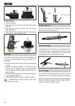
Engine start
Check if the traction lever (15) is disengaged and
the speed lever (21) is on neutral to avoid a
sudden and uncontrolled movement as the engine
starts.
1.
Close the air filter, place the air lever (38) to the left;
2.
Open the fuel tap (38) place on
position “ON”, the
knob must be on the right.
3.
Place the throttle knob in the middle;
4.
Pull slowly the starter grip (40) until feel some
resistance and then pull harder until the engine starts
working;
5.
After about 30 seconds, open the air filter, move the
ai
r lever (38) until it’s placed on the right;
Do not close the air filter if the engine is warm or
if the air temperature is high.
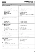
Traction
1.
Press the traction locking lever (16);
2.
Grab the traction lever (15) and the traction shaft
(29) starts running;
3.
When you release the traction lever the traction shaft
stops;
Speed lever
1.
The speed lever (21) must be handled when the
traction lever is loose.
2.
The speed lever allows to select four positions
according to the desired operation: Reverse (R),
Neutral (Ø), Slow (S) and Fast (F);
3.
After selecting the desired speed grab the traction
lever (16) and the traction shaft starts running;
The starting movement may be quite abrupt.
To start the
traction shaft
To stop the
traction shaft
1.
2.
3.
Summary of Contents for VIME7
Page 1: ...PT EN MOTOENXADA GASOLINA PETROL TILLER ES FR MOTOAZADA GASOLINA MOTOBINEUSE A ESSENCE VIME7 ...
Page 5: ...5 DESCRIÇÃO DA FERRAMENTA E CONTEÚDO DA EMBALAGEM MOTO ENXADA GASOLINA VIME7 ...
Page 21: ...21 DESCRIPCIÓN DEL APARATO Y CONTENIDO DEL EMBALAJE MOTOAZADA GASOLINA VIME7 ...
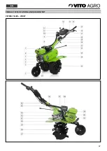
Page 37: ...37 PRODUCT SPECIFICATIONS AND BOX CONTENT PETROL TILLER VIME7 ...
Page 53: ...53 DESCRIPTION DE L APPAREIL ET DU CONTENU DE L EMBALLAGE MOTOBINEUSE À ESSENCE VIME7 ...
Page 70: ......
Page 71: ......
Page 72: ...VIME7_REV01_JUN21 ...


