background image


Instructions for Use


47 


10   Warranty and Returns 

Integrated  Technologies  Limited  (ITL)  warrants  the  Co-mix  product,  when 

purchased  new  and  installed  and  operated  in  accordance  with  the 

instructions  of  this  manual,  to  be  free  from  defects  in  materials  and 

workmanship,  and  will  repair  or  replace,  at  their  discretion,  any  unit  or 

accessory which exhibits such defects. 


In  no  event  will  ITL  be  liable  for  any  indirect,  incidental  or  consequential 

damages resulting from any defect or warranty claim. 


NOTE


Unspecified use or unauthorised modification of any part of the Co-

mix unit or its accessories or the use or attachment of any adaptor 

or peripheral not supplied, specified or sanctioned by ITL will 

invalidate this warranty. 


This warranty is provided to the original purchaser of the product for one year 

from the date of purchase. 


Under the terms of this warranty, the product must be returned in its original 

packaging, transportation prepaid by the sender, with a copy of the Proof of 

Purchase and a detailed description of the problem. 


WARNING


The product must be decontaminated using the procedure 

detailed in section 8.3 and a Certificate of Decontamination 

supplied with any return. If the product is considered too 

hazardous to be shipped, please contact ITL on the number 

given on page 2 of this manual for further instructions. 


Please contact your distributor (or ITL on the number given on page 2 of this 

manual) to receive authorisation to return the product. 


Summary of Contents for Co-mix

Page 1: ...Instructions for Use...

Page 2: ...nge without notice ITL assumes no responsibility for any errors that may appear in this or related documentation Document V501001 Revision 3 1412 Vitl is the brand name for Integrated Technologies own...

Page 3: ...result in severe injury or death WARNING Indicates a hazardous situation which could if not avoided result in severe injury or death or severely damage the unit CAUTION Indicates a hazardous situation...

Page 4: ...empting to operate the unit Improper use of this unit or its accessories may impair their functionality and invalidate the manufacturer s warranty Unit Handling Precautions CAUTION Care should be take...

Page 5: ...y earthed mains supply with appropriate earth leakage and over current protection WARNING Always ensure that the mains power connector is securely inserted into the rear of the unit and any excess pow...

Page 6: ...when mixing and vortexing WARNING Injury can occur from flying plates and tubes if they are not correctly inserted or if the maximum recommended mixing speed or total load weight is exceeded Always e...

Page 7: ...injury or death DANGER The externally accessible unit fuse will only blow under an extreme internal fault condition This fuse should only be changed after the unit has been thoroughly inspected by a...

Page 8: ...10 1 2010 EN 61010 2 051 2003 UL 61010 1 2001 2nd Edition CAN C22 2 CSA 61010 1 EMC EN 61326 2006 Class B FCC CFR 47 Parts 15 107 and 15 109 Class B RoHS and WEEE Directive Compliance This product is...

Page 9: ...terface 6 1 Plate Mixer Plate Holder 6 3 Plate Clamping Lever 6 3 2 Tube Vortexer 6 4 Unit Label and Serial Number 4 Mains Power Switch 5 Mains Power Inlet 5 External Fuse Access Cover 8 1 Mains Power...

Page 10: ...lowing accessories Table 3 Unit Accessories Mains power cord varies according to country of use 5 11 96 well PCR plate and 0 2ml tube adaptor block 6 3 6 3 3 24 well 0 5ml tube adaptor block 6 3 6 3 4...

Page 11: ...ions listed in section 2 Install and test the Co mix unit using the following procedure 1 Place the Co mix unit on the suitably selected working surface as specified above ensuring that the ventilatio...

Page 12: ...LCD touchscreen with page selection tabs down the left hand side of the display and function buttons along the bottom Page Selection Tabs Control and Status Function and Option buttons The Co mix is...

Page 13: ...he program s ID and the assigned speed and time parameters Program ID Favourite Pre defined Speed Time To load a program use the Home button to jump to the top of the program grid list or the Next and...

Page 14: ...us menu Add remove Favourite program 7 1 1 New Edit or Delete program 7 1 Change program ID or Info 7 1 3 Change user program Adaptor type 7 1 3 Unlock program speed and time 7 1 3 Increase or Decreas...

Page 15: ...matic Tube Vortexing 6 4 1 Manual Tube Vortexing 6 4 1 Batch Tube Vortexing 6 4 2 Add favourite program 7 1 1 Create new program 7 1 2 Edit user defined program 7 1 3 Change program speed and time 7 1...

Page 16: ...nform to the ANSI SBS Standard for Microplates to ensure secure positioning in the plate holder The maximum permissible mixing speed for DWPs and Adaptor Blocks or other plates over 80g is 2000 RPM Th...

Page 17: ...immediate needs The mixer speed can be set between 200 RPM and 3000 RPM and the time between 5 seconds and 28 days Home Previous Next Tools Accept To load the MIX program select the Mixer page tab the...

Page 18: ...MIX program the Increase and Decrease buttons are always enabled to allow the speed and time parameters to be freely changed even when the mixer is running Place the plate or adaptor block vertically...

Page 19: ...ll automatically close to firmly grip the plate or adaptor block and the specified mixing program will be run The mixing timer will now count down each second until it reaches zero or the Stop button...

Page 20: ...orarily disabled by pressing the Mute button The display will return to the previous screen ready to accept the next plate to be mixed Pressing the Programs button will close the plate clamping mechan...

Page 21: ...0 30 5 to 50 x PCR 96 96 well PCR plate 0 2ml tubes or strips 1650 30 5 to 50 1 MTP 384 384 well MTP 2000 15 10 to 60 x DWP 384 384 well DWP 2000 15 10 to 60 x PCR 384 384 well PCR plate 2600 15 10 to...

Page 22: ...ined variants of the pre defined programs Place the plate or adaptor block into the plate holder making sure it sitting flat on the base of the holder and then press the Start button to close the clam...

Page 23: ...suring that they are securely and fully pushed down in the wells 3 Insert the adaptor block into the plate holder on the unit 4 After mixing remove the adaptor block from the unit and then remove the...

Page 24: ...m improper vortexing of tubes Never vortex open topped tubes Always use sealed tubes Never vortex tubes made of glass or other fragile materials Not suitable for flasks or other flat bottomed vessels...

Page 25: ...Mute Start To vortex a tube simply press the tube down onto the centre of the vortexer pad and vortexing will automatically start at the programmed speed The timer will count down each second and vort...

Page 26: ...when next required See sections 6 4 3 and 7 3 for details The unit clicks once to acknowledge when the tube has been pressed onto the vortexer pad and beeps once when the programmed time has elapsed T...

Page 27: ...pressure so that there is still sufficient contact with the pad to maintain the vortexing action but without being unduly strenuous on the user If desired this mode can be permanently enabled for all...

Page 28: ...ms the user can create variants of the existing ones This allows new programs to be developed and optimised for the specific plate type sample assay and fill volume being used Home Previous Next Tools...

Page 29: ...se will be regularly used Thus to help organise the full list preferred programs can be added to a favourites list which always appears at the top of the program selection list To add a program to the...

Page 30: ...available when Protected mode is enabled See selection 7 4 4 for details This will create a new copy of the selected program and pop up the program ID editing keyboard Shift Delete Cancel Left Right A...

Page 31: ...unctions Exit ID Info Adaptor Unlock These editing functions allow the program ID Info text and associated Adaptor block type to be changed as described in Table 11 Table 11 Program Editing Functions...

Page 32: ...eing used Any changes to these parameters are automatically saved to memory for next time Pressing the Profile button brings up the advanced program profiling menu which allows a sequence of up to 20...

Page 33: ...Profile Step Parameters Parameter Purpose Range RPM Mixing speed Automatically limited to 2000 RPM when the program specifies the use of an adopter block 200 to 3000 RPM TIME Mixing step duration spe...

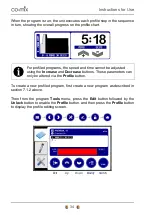
Page 34: ...sted using the Increase and Decrease buttons These parameters can only be altered via the Profile button To create a new profiled program first create a new program as described in section 7 1 2 above...

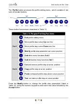
Page 35: ...rsor Up one line Move profile step cursor Down one line Modify profile step parameters at cursor position Switch to menu functions Set 2 Set 2 Switch back to menu functions Set 1 Cut and remove profil...

Page 36: ...ept 4 Enter the new SECS value followed by Accept 5 Press Accept again skips RAMP When all six values had been accepted the new settings are saved and the display returns to the previous profile editi...

Page 37: ...ste Modify 7 3 Vortexer Program Tools The Co mix can store up to 99 user defined vortexing programs allowing specific programs to be developed and optimised for different tube types sample solutions a...

Page 38: ...in the more detail in the following sub sections Table 15 User Preferences and Options Beeper volume Muted Low Medium High 7 4 1 Touchscreen button click volume Disabled Quiet Loud 7 4 1 LCD backligh...

Page 39: ...ditions 7 4 3 Cooling Fan Operating Mode The unit s internal cooling fan draws air in from around the plate holder and gently blows warm air out of the ventilation slots in the base of the unit It is...

Page 40: ...ation If processing large batches of tubes it may be desirable for the vortexer to run on after the tube has been removed This auto Restart mode can be permanently enabled for all vortexer programs by...

Page 41: ...nly be replaced by a suitably qualified engineer DANGER The unit fuse will only blow as a result of an internal unit fault This fuse should only be changed after the unit has been thoroughly inspected...

Page 42: ...nism 6 Clean around the gap between the plate holder and casework to remove any build up of debris avoiding pushing it into the unit 7 Clean along the spill gutter strip at the rear of the unit 8 Clea...

Page 43: ...oroughly clean all outside surfaces of the product including any accessories power cords manuals packaging etc with a damp cloth soaked with suitable disinfectant solution such as Virkon Allow to dry...

Page 44: ...e completely dry and free of any condensation before being packed 8 5 Product Disposal At end of life this product must be disposed of in accordance with your local authority regulations for the dispo...

Page 45: ...ed for optimum performance 6 3 1 Mixing time too short Increase mixing time to ensure adequate mixing 6 3 1 Lid wetting or sample leakage Reduce mixing speed or fill volume 6 3 Vortexer Does Not Opera...

Page 46: ...assistance 8 E23 E24 Mixer overloaded or jammed Switch off unit and inspect plate holder for obstructions 8 2 E25 Mixing load unbalanced Ensure unit correctly installed on solid working surface 5 Ensu...

Page 47: ...r or peripheral not supplied specified or sanctioned by ITL will invalidate this warranty This warranty is provided to the original purchaser of the product for one year from the date of purchase Unde...

Page 48: ...0V 20x5mm Operating Environment Temperature Range Relative Humidity Range Maximum Operating Altitude 10 to 38 C 20 to 85 non condensing 2000 m above sea level Storage and Transportation Temperature Ra...

Page 49: ...es MTP Microtiter plate PCR Polymerase Chain Reaction Pellet A small densely packed mass Created for example via the centrifugation of a suspension PPE Personal Protective Equipment Re suspending Diss...

Page 50: ...ing Programs 27 7 Advanced Set up Features 28 7 1 Mixer Program Tools 28 7 1 1 Favourite Programs List 29 7 1 2 Creating a New User defined Program 30 7 1 3 Changing the Program ID Info Adaptor Type a...

Page 51: ...Menu Structure and Button Presses 15 Table 7 Supported Plate and Tube Types 16 Table 8 Pre defined Mixing Programs 21 Table 9 Supported Vortexer Tube Types 24 Table 10 Program Tools Options 29 Table...

Reviews: