background image

20 

(A)


Current  Mode

:  After  entering  Video  REC  mode,  the 

mark  of  Current  Mode  showed  as 

  representing 

video  is  recording.    Press  the  button 

  to  record 

video,  and  the  Current  Mode  turns  to  be 

  from 

.   

(B)


Recording  Time:  After  recording,  recording  time  will  be 
counted  in  second.  Each  file  can  be  recorded  maximum 
one hour.   

(4)


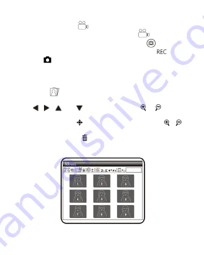
Album

:  a  model  to  browse  photos  by  listing  all  shot 

pictures.  Please  refer  to  the  following  image.  Use  buttons  of 

  and 

  to  select  images  ,  use

  &

  to  swift 

page, one page has 9 files.     

Press the button 

  to open it in full screen, and use

&


to enlarge or reduce photo size.     
Press the button of 

  to delete the image, and the inquiry   

window will be displayed before the deletion. Select (Yes) for   
deletion and (No) for not.                         


Summary of Contents for VT300 PLUS

Page 1: ...VT300 PLUS User s Guide Digital Portable Microscope Version 2 1A...

Page 2: ......

Page 3: ...croscope 6 1 4 Microscope Programming Functions 8 1 5 External Interfaces of Microscope 24 2 Program Installation 27 2 1 Insert CD Step 1 27 2 2 Install Application Program Step 2 27 2 3 Quit Installa...

Page 4: ...ry for 6 to 8 hours for the first time Name Qty Name Qty Portable Microscope 1 Li ion Battery 1 USB2 0 Cable 1 User s Guide 1 Adaptor 1 Clean Cloth 1 Calibrator 1 Wrist Strip 1 1 2 Functions of Micros...

Page 5: ...tion 1 4 3 Zoom In the button is applied to zoom in digital image 4 Charging Display Light The red light is to show the charging status if it is on The red light will turn off when the charging is com...

Page 6: ...the center of the LCD Display Or the button is used to next sequent left function 11 Confirmation Button a switching button between special effects under observing mode and video recording mode please...

Page 7: ...in the image by pressing any button insert slender clip into the hole to trigger the RESET button After RESET please switch off on power button or plug out in power cable 19 USB Connection Port the po...

Page 8: ...long shot need tuning the clear focus between B C for continuous magnification 1 10x C is low optical magnification 10x and D is High optical magnification 30x You may find symbol represents the magn...

Page 9: ...t Rotate the Focus dial next to 10X s right side then slightly tuning so that to get the best image Photography is same as the way of camera and scene mode is selectable please refer to B of item 1 of...

Page 10: ...in the programming interface Press the Function Menu Delete button to switch functional modes in the Camera In other modes press the button of Preview Photo Back to back to the Menu and switch functi...

Page 11: ...select the modes by using buttons of B 1 Automatic mode default B 2 Camera mode LED will turn off automatically in this mode B 3 White mode for example the observed articles made of shining materials...

Page 12: ...brightness is divided into the following 8 levels level 0 no light level 4 level 1 level 5 level 2 level 6 level 3 level 7 most bright E Battery Status the state is divided into three types including...

Page 13: ...justing the black indicator on the wheel of Focus Please refer to the following Low Mag L High Mag H Digital magnification rate can be adjusted by the buttons of zoom out and zoom in The magnification...

Page 14: ...e listed as follows 0 1 2 3 4 5 6 7 8 H Alignment in Range press the button for a long time to display the sign of alignment in range and press it again to shut down the sign Use the sign to assist in...

Page 15: ...se the flushing way Please refer to item 2 of Section 1 3 The scales will be varied with magnification rates changes The unit in the scale is m The following scales are highly precise and provided for...

Page 16: ...note any L H since machine is not able to know the preview situation Below chart is the FOV for different magnification and stage of enlargement Field of View of 10x Optical zoom unit mm Stage L0 L1...

Page 17: ...the look up table before start measurement To begin measurement please open AP and choose Measurement mode see as below fig Then choose Setting Ruler After enter Setting Ruler please create scale fil...

Page 18: ...ing photo by button After it enlarges the photo it can move the photo up down left right through Press button to return the original window status then it can allow to swift next photo L Comparison mo...

Page 19: ...Comparison mode See below illustration At the moment all buttons are same function but only allow to control the right window Press button to swift next photo and press to return the preview photo Pre...

Page 20: ...tton of Camera in the mode of Video Play to enter the interface of file selection Select the demanded file as in the following image After selection press the button of to play Use buttons of to selec...

Page 21: ...the button of to play the last file E Hide the Panel Press the button of to hide the control panel F Next File Press the button of to play the next file G Current Time Total time for the playing video...

Page 22: ...in second Each file can be recorded maximum one hour 4 Album a model to browse photos by listing all shot pictures Please refer to the following image Use buttons of and to select images use to swift...

Page 23: ...to operate by microscope C Removable disk window will pop up or enter my computer an device of removable disk is shown on the screen 6 PC Cam Mode of computer camera PC Camera In this mode the machin...

Page 24: ...7 Set Up a model to set the system and provides seven functions for selection according to your own orientation Please refer to the following setting image Press buttons of and to select and adjust an...

Page 25: ...rect image s contrast and color We suggest you switch on automatic white balance to achieve optimum result E Sharpness Adjust image sharpness and highlight edge The value is higher the sharpness is mo...

Page 26: ...splay the system time 1 5 External Interfaces of Microscope The machine contains many external interfaces The following contents give instructions about assembly of the accessories Please use accessor...

Page 27: ...Please refer to the following image for the USB connection Caution It is highly suggested to remove battery while connect machine to PC 2 USB Power Supply provide power supply for the machine by USB...

Page 28: ...he written face up and complying with positive and negative poles correctly Close battery cover finally Please refer to the following image 4 Install Wrist Strap Remove battery cover Hang the wrist st...

Page 29: ...27 2 Program Installation 2 1 Execute Auto run program Step 1 2 2 Step 2 2 3 Step 3...

Page 30: ...go wrong by strong collision vibration or distortion 4 Shut down the machine before cutting off the power supply or removing the battery do not forced cut off the power supply or remove the battery 5...

Page 31: ...n Optical Zoom 1x 10 x continue and 30 x 5 x Digital Zoom Joint DC IN Terminal mini USB joint Lithium Battery Model NP 120 Voltage 3 7 V USB Power Supply Device Adaptor AC Transformer Output DC 5 0 1A...

Page 32: ...e battery or power supply device to avoid fire and electric shock 5 Do not look steadily at auxiliary sources after switching on the host as it is harmful to your eyes 6 Please use related products pr...

Page 33: ...hine Type Serial Number Purchase Date Day Month Year Purchaser Purchaser Address Email Machine Type Distributor Seal for Confirmation Stamp is necessary for validation of the Warranty Distributor s se...

Page 34: ...etc Services caused by any of the following situations in the period of the warranty shall not be provided free of charge 1 Improper using or self entrust any other with disassembly repair or refittin...

Page 35: ......

Page 36: ...MicroLinks Technology Corp All rights reserved HTTP WWW VITINY COM...

Reviews: