background image

VT-PTZ Series 


17 

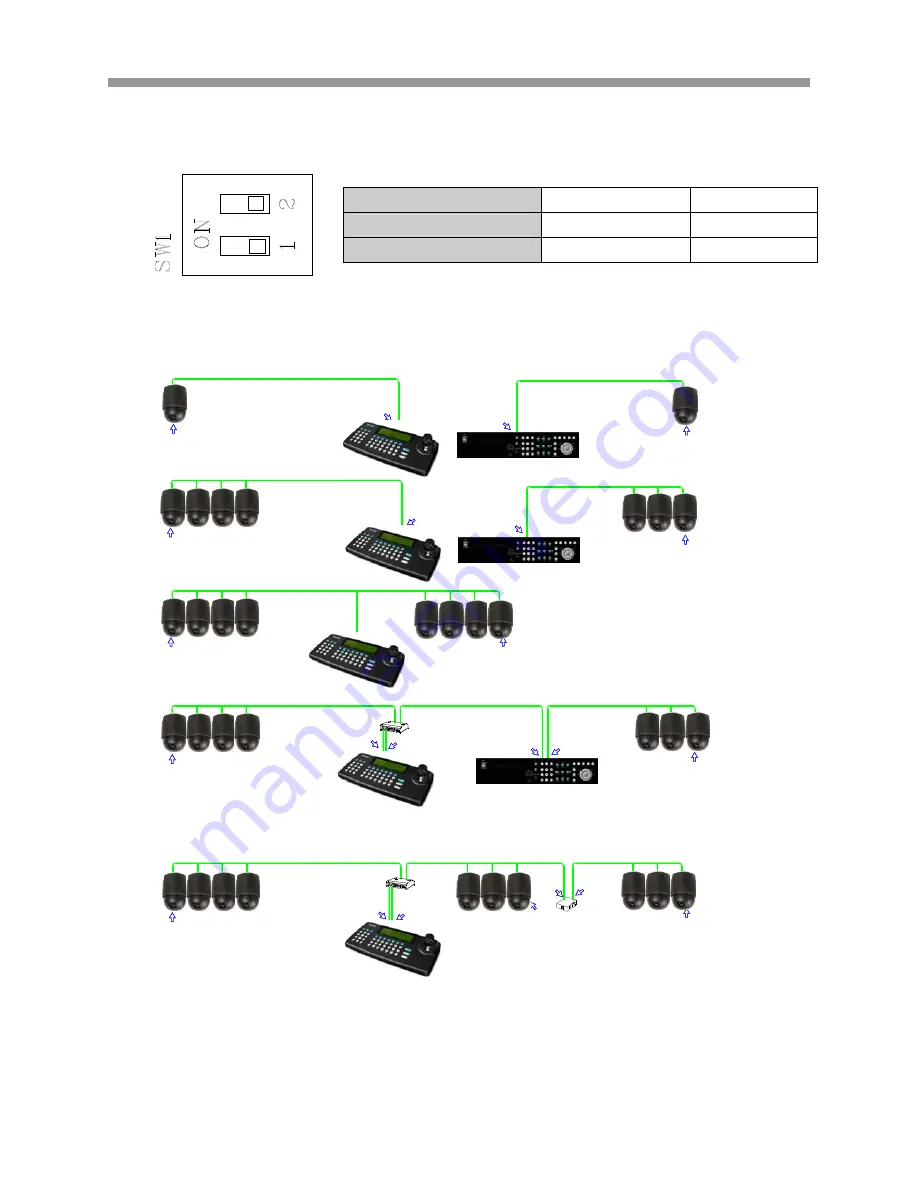
The following diagram displays the dip switch settings for termination.   


The following diagrams are some sample examples of Termination configuration.   


SW1 1 

Terminated ON ON 

Not terminated 

OFF 

OFF 

SW1:Termination ON

SW

!:

Te

rm

in

at

io

n ON

T

E

RMIN

ATI

O

N

 ON

SW1:Termination ON

DVR Termination ON

S1:Dome1 port  Termination ON

S1:Dome1 port  Termination ON

SW1:Termination ON

SW1:Termination ON

DVR Termination ON

SW1:Termination ON

SW1:Termination ON

SW1:Termination ON

SW1:Termination ON

S1:Dome1 port  Termination ON

S4:DVR port  Termination ON

DVR Termination ON

DVR Termination ON

SW1:Termination ON

S1:Dome1 port  Termination ON

S3:Dome2 port  Termination ON

SW1:Termination ON

Summary of Contents for VT-PTZ Series

Page 1: ...m slow to medium panning with smooth Vector Scan 8 Tours Each tour consists up to 64 Preset Pattern Scan and other Tours Tour can be expanded up to 500 different functions using nested Tours Smooth Ve...

Page 2: ...ging contains the following contents 1 One Xpress Dome 2 One Bubble Ring 3 One Instruction Manual 4 Three Mounting Screws 5 Three Plastic Anchors 6 One Three Pin Connector 7 One Four Pin Connector 8 T...

Page 3: ...htning flash with arrowhead symbol within an equilateral triangle is intended to alert the user to the presence of uninsulated dangerous voltage within the product s enclosure that may be of sufficien...

Page 4: ...anslated into any language in any form by any means without prior written permission of Vitek Industrial Video Products Inc Vitek makes no warranties for damages resulting from corrupted or lost data...

Page 5: ...ion If this equipment does cause harmful interference to radio or television reception which can be determined by turning the equipment off and on the user is encouraged to try to correct the interfer...

Page 6: ...e note that the Xpress Domes are intended for surveillance use and should never be used in a manner that invades other people s privacy or contravenes international or domestic privacy act and its reg...

Page 7: ...ock Internal inspections alterations and repairs should be conducted by qualified service personnel authorized by the equipment distributor or Vitek customer help desk z Stop operating the equipment i...

Page 8: ...Do not cut damage alter or place heavy items on the power cord Any of these actions may cause an electrical short circuit which may lead to fire or electrical shock z Do not handle the device or power...

Page 9: ...F 104 F and humidity below 90 The normal operating power source for this device is 24VDC 3amps or 24VAC 40VAC PREVENTING MALFUNCTION z Avoid Strong Magnetic Fields Never place the Speed Dome in close...

Page 10: ...E COMMUNICATION SPEED 19 2 6 WIRE CONNECTIONS 19 2 6 1 RS485 422 Connection 19 2 6 2 Alarm connection 20 2 7 MOUNTING THE SPEED DOME 22 2 8 POWER ON AND BOOT UP SEQUENCE 23 2 9 MAIN SCREEN DISPLAY 24...

Page 11: ...ALARM 47 3 2 2 SAVE AND EXIT 49 3 2 3 DELETING AN ALARM 49 3 2 4 SAMPLE SCENARIO 50 3 3 SCREEN 51 3 3 1 LANGUAGE 51 3 3 2 PRIVACY ZONE 51 3 3 2 1 Programming a privacy zone 52 3 3 2 2 Alternate method...

Page 12: ...N 68 3 4 6 SHARPNESS CONTROL 69 3 4 7 DIGITAL ZOOM 69 3 4 8 NIGHT SHOT VT PTZ26 ONLY 69 3 4 8 1 Mode 70 3 4 8 2 Local Control 70 3 4 9 CAMERA DEFAULT 70 3 4 10 SAVE AND EXIT 70 3 5 SETUP 71 3 5 1 STAB...

Page 13: ...VT PTZ Series 12 3 5 9 SYSTEM INFORMATION 81 3 5 10 EXIT 81 V GLOSSARY 83 VI FUNCTION SHORTCUTS 86...

Page 14: ...d IR cut filter removal mechanism VT PTZ26 only Functions 248 Presets programmed with view direction zoom BLC 4 Patterns record and play back user preference of surveillance path up to 240 sec 16 Scan...

Page 15: ...st Connection Addressable up to 999 camera IDs Extendable up to 3999 in factory mode Built in RS 485 422 receiver driver On site software upgrade and upload download of programmed data into the Xpress...

Page 16: ...ess Keyboard VT KBD1 and a variety of external switching devices such as the Saga Series Digital Video Recorders VT ST and VT XL may be incorporated to accommodate the needs from the small to large su...

Page 17: ...to on position to terminate a line of communication On other devices such as a DVR an appropriate termination must be set by either dip switches or jumpers to prevent any communication errors Alarm In...

Page 18: ...tion ON TERMINATION ON SW1 Termination ON DVR Termination ON S1 Dome1 port Termination ON S1 Dome1 port Termination ON SW1 Termination ON SW1 Termination ON DVR Termination ON SW1 Termination ON SW1 T...

Page 19: ...more than 16 dome cameras are installed using two or more DVRs the following formula is useful to determine the Dome ID ID 16x n 1 m where n number of DVR m Camera Port Please refer to the following...

Page 20: ...N On On On Off DC Off Off Off On KL On Off Off On PS Off On Off On SE On On Off On ST Off Off On On VL On Off On On DI Off On On On 2 5 SELECTING THE COMMUNICATION SPEED Dip Switches S6 Baud Rate 1 2...

Page 21: ...hain connection requires a splitter as the RS 485 native connection does not support a Star connection layout Distance The maximum distance for the RS 485 connection is 1 2 Km Any distance exceeding 1...

Page 22: ...a normally closed circuit to activate a variety of external devices such as sirens buzzers or lights 3 NO A NO B Connect the wire for the alarm output using the normally open circuit 4 GND All the gro...

Page 23: ...the dip switches and all the wiring have been properly configured the Speed dome can be mounted in a variety of configuration using the available accessories The product name here itself should be mo...

Page 24: ...T UP SEQUENCE When the Speed Dome is twisted in and locked onto the base module it will be powered on and will run its self diagnostic boot up sequence It will run a series of self tests on the RAM pa...

Page 25: ...equence is disturbed or is malfunctioning then an error message will appear to the specific function 2 9 MAIN SCREEN DISPLAY Alarm Display Information Program No Function Title Dome Camera Title Compa...

Page 26: ...d Press the number for the camera and then press the CAM button sequentially to select a specific camera For example pressing 4 then CAM will select Speed Dome number 4 Pressing 3 8 and then CAM will...

Page 27: ...ange Values LEFT OR RIGHT 4 Navigate through menu items UP OR DOWN Navigate through menu items DOWN Complete Title editing 1 Change Value TWIST LEFT OR RIGHT 2 Enter Title Edit mode SHIFT JOYSTICK MOV...

Page 28: ...e Xpress Dome resumes automatically its programmed function after it has been idle for a specified time For example if someone interrupts any of the programmed function then the Xpress Dome will resum...

Page 29: ...to be run 3 1 1 3 Time Select from 10 seconds to 240 seconds after which the Xpress Dome resumes its programmed function The default is 60 seconds 3 1 1 4 Operation Enable or Disable the HOME FUNCTIO...

Page 30: ...tion or be programmed into the TOUR Note The PRESET menu can be accessed directly from the main screen by pressing the PRESET button There are 31 pages of preset programming window Each page holds eig...

Page 31: ...anually as needed Move the joystick to highlight the desired function and then twist the joystick to toggle between A and M Manual for FOCUS and IRIS O On and F for BLC 6 The TITLE is entered automati...

Page 32: ...FT button and move the joystick around to select the desired pan tilt and zoom position 4 Let go of the SHIFT button to finish programming the preset position 3 1 2 3 Deleting a programmed preset posi...

Page 33: ...d Exit Save the changes and exits to the main FUNCTION menu 3 1 3 PATTERN PATTERN memorizes the movement controlled by user and duplicates the movement The movement can be any combination of PAN TILT...

Page 34: ...tick around and zoom in and out to create the path of the pattern 4 Press FOCUS button to program the path Please note the duration of the pattern and the total duration of the pattern 5 The TITLE is...

Page 35: ...empty pattern number 2 Press and hold down the SHIFT button and the Select Position will start flashing 3 Do not let go of the SHIFT button and move the joystick and zoom in and out to create the path...

Page 36: ...ss the OFF button to delete the selected preset position 3 1 3 4 Save and Exit Save the changes and exits to the main FUNCTION menu Note If the total programming time reaches 240 seconds it will autom...

Page 37: ...ess Dome is capable of moving the three coordinates while moving from one point to another Note The SCAN menu can be accessed directly from the main screen by pressing the SCAN button 3 1 4 1 Programm...

Page 38: ...and move the joystick to select the desired pan tilt and zoom position This will be the starting point of the SCAN 5 Press the FOCUS button to program the selected location 6 Highlight END and then t...

Page 39: ...and move the joystick around to select the desired pan tilt and zoom position 3 When the desired location is selected let go of the SHIFT button to finish programming the starting point 4 Highlight E...

Page 40: ...the end point 3 1 4 3 Direction Select the direction of the scan Available options are CW Clockwise and CCW Counter Clockwise The default is CCW 3 1 4 4 Swap Swap exchanges the START and the END point...

Page 41: ...set 02 Preset 03 Tour 02 Tour 03 Tour 02 Preset 05 Preset 06 Tour 04 Preset 05 Tour 03 Preset 07 Pattern 01 Tour 04 Preset 08 Preset 05 Pattern 01 Example 1 Tour 01 will run as follow when executed Pr...

Page 42: ...st the joystick to customize the Tour title 3 Select an empty location 4 Press the PRESET button 5 When the PRESET button is pressed the first program is entered automatically Move the joystick to the...

Page 43: ...lt is 3 seconds Available dwell time is from 1 to 99 seconds 8 Repeat steps 3 through 7 for additional PRESET programs to be run Please note that the preset programs must be preprogrammed before they...

Page 44: ...n The default is F 5 Select the dwell time for the camera to stay at the view after the pattern program has run The default is 3 seconds Available dwell time is from 1 to 99 seconds 6 Repeat steps 1 t...

Page 45: ...ble speeds F Fast M Medium and S Slow for the camera to move to the beginning of the scan The default is F 5 Select the dwell time for the camera to stay at the view after the scan program has run The...

Page 46: ...udes five preset programs one scan program and one pattern program to be run sequentially 2 The example to the left shows Tour 2 which includes a combination of preset programs one pattern and Tour 1...

Page 47: ...ous Next Page Highlight and move the joystick left or right to switch between the eight available pages per tour for a total of 64 functions within a tour 3 1 5 7 Save and Exit Save the changes and ex...

Page 48: ...AND TOUR to respond immediately and send the camera s view to the designated area 3 2 1 PROGRAMMING THE ALARM 1 Highlight an alarm number by moving the joystick up or down 2 Highlight the FUNCTION an...

Page 49: ...circuit Available options are NC Normally Closed NO Normally Open and OFF The default is OFF 5 Select the alarm output Available options are R01 Relay 01 R02 Relay 02 and OFF 6 Select the amount of se...

Page 50: ...eries 49 3 2 2 SAVE AND EXIT Save the changes and exits to the main FUNCTION menu 3 2 3 DELETING AN ALARM 1 Move the joystick to highlight the desired alarm 2 Press the OFF button to delete the select...

Page 51: ...led as Example001 when the Normally Closed Circuit is broken As priority level 0 supersedes all other alarms Autoscan 1 will be executed before any other functions listed with other alarms and at the...

Page 52: ...N menu consists of the screen related features where the LANGUAGE PRIVACY ZONE NORTH DIRECTION ZONE TITLE and CAMERA TITLE are configured 3 3 1 LANGUAGE The only available language supported at this t...

Page 53: ...ne number and twist the joystick to enter the programming window Select Position will start flashing 2 Move the joystick around to select the desired pan tilt and zoom position What is shown on the sc...

Page 54: ...ones MASK or V OFF Video OFF 3 3 2 2 Alternate method of programming a privacy zone 1 Highlight a privacy zone number 2 Press and hold down the SHIFT button and the Select Position will start flashing...

Page 55: ...ish programming the preset position 3 3 2 3 Privacy zones displayed on screen per type 1 Privacy zone shown when using MASK option 2 Privacy zone shown when using V OFF option 3 3 2 4 Deleting a priva...

Page 56: ...3 3 NORTH DIRECTION North direction allows the user to keep track of where the direction of North is For example if the Xpress Dome is installed at a location where there may be no points of reference...

Page 57: ...Position 1 Twist the joystick to enter the programming mode Select Position will start flashing 2 Move the joystick around to select the new position for the north direction and then press the FOCUS...

Page 58: ...3 3 4 ZONE TITLE There are a total of 24 available zone titles that can be programmed between specific areas 3 3 4 1 Zone Title Display ON OFF Select the zone title display option on or off 3 3 4 2 Pr...

Page 59: ...t and zoom position 3 Press the FOCUS button to program the selected location 4 Move the joystick to the END column of the same zone number 5 Twist the joystick and Select Position will start flashing...

Page 60: ...title 9 Move the Joystick up or down to finish entering the title 3 3 4 3 Alternate method of programming a zone title 1 Select an empty zone number and move the joystick to START column 2 Press and h...

Page 61: ...itle 4 Move the joystick to the END column of the same zone number 5 Press and hold the SHIFT button and Select Position will start flashing Do not let go of the joystick and it around to select the d...

Page 62: ...our pages of zone title pages There are a total of 24 zone titles available 3 3 4 5 Save and Exit Save the changes and exits to the main SCREEN menu 3 3 4 CAMERA TITLE The Xpress Dome can be labeled u...

Page 63: ...Display Select the display mode of the camera title ON or OFF 3 3 4 3 Position Select the display mode of the X and Y coordinates of the camera s view 3 3 4 4 Save and Exit Save the changes and exits...

Page 64: ...ROL WHITE BALANCE CONTROL AUTOMATIC EXPOSURE CONTROL BACK LIGHT COMPENSATION SHARPNESS DIGITAL ZOOM and CAMERA DEFAULT 3 4 1 FOCUS CONTROL 3 4 1 1 Mode Available focus modes are AUTO and MANUAL When s...

Page 65: ...sts the white balance of the picture As different lighting conditions affect the picture differently it enables the camera to automatically or manually adjust to different environments for optimal pic...

Page 66: ...ries 65 3 4 2 2 R Gain Red Gain Adjust the Red Gain in MANUAL mode 3 4 2 3 B Gain Blue Gain Adjust the Blue Gain in MANUAL mode 3 4 2 4 Exit Exit from the WB CONTROL 3 4 3 AE CONTROL AUTOMATIC EXPOSUR...

Page 67: ...MANUAL IRIS PRIORITY SHUTTER PRIORITY and BRIGHTNESS 3 4 3 2 Slow Shutter Limits the Digital Slow Shutter Speed Available options are 1 8 1 15 1 30 1 60 and Full Auto 3 4 3 3 Iris Adjust the Iris valu...

Page 68: ...ss Adjust the brightness of the picture Available options are 0 through 31 3 4 3 6 Shutter Adjust the shutter speed of the camera Available options are 1 1 through 1 30000 3 4 3 7 Exit Exit to the Cam...

Page 69: ...the phase within the camera module and select the External mode to adjust with a variety of other devices such as monitors switchers cameras and multiplexers 3 4 4 2 Phase Select the Phase frequency o...

Page 70: ...rough 63 The default value is 9 3 4 7 DIGITAL ZOOM Digital Zoom further enhances the zoom ratio by digitally magnifying the picture Available options are 2X 4X and MAX 12X The default is OFF 3 4 8 NIG...

Page 71: ...he environmental changes in Auto mode The camera can be manually switched between day and night modes in Manual mode 3 4 8 2 Local Control Manually turn on or off the Night mode The default setting is...

Page 72: ...e is installed in an unstable environment e g on top of a skyscraper windy environment and such The default is OFF 3 5 2 FLIP The Flip is a useful tool to follow an object or a human being passing dir...

Page 73: ...ult is FAST 3 5 4 PANNING RANGE The Xpress Dome s movement of range can be restricted depending on the environment For example when the Xpress Dome is installed in a corner or near a wall it makes sen...

Page 74: ...to select the desired pan position 3 Press the Focus button to program the selected location 4 Highlight the Left Pan Limit 5 Twist the joystick to activate the programming window Select Position will...

Page 75: ...osite of the intended limits If such is the case simply highlight the SWAP RIGHT LEFT and twist the joystick to swap the right and left pan limit 3 5 4 2 Alternate method of programming Pan Range Limi...

Page 76: ...ired pan position 4 Let go of the SHIFT button to finish programming the pan position 5 Highlight the Left Pan Limit 6 Press and hold down the SHIFT button and the Select Position will start flashing...

Page 77: ...s and exit to the SETUP menu 3 5 5 TILT OVER ANGLE Tilt Over Angle sets the limit to the horizontal view angle so that the trim ring or the housing or the ceiling does not obstruct the view of the cam...

Page 78: ...features a sensor within its mechanism to sense and retain the exact position of each and every movement so that any programmed functions and features are replicated without error time after time Howe...

Page 79: ...e will reset and reinitialize just as when the Xpress Dome was first powered on The point of origin will be reset back to when the Xpress dome was powered on 3 5 6 2 Origin Position Move If the Xpress...

Page 80: ...tton to program the new point of origin and exit to Calibration menu 3 5 6 3 Origin Offset Enable or disable the point of origin offset The default is DISABLE 3 5 6 4 Auto Calibration Constantly monit...

Page 81: ...he settings and exit to the Setup menu 3 5 7 FACTORY DEFAULT Revert all settings back to factory default 3 5 8 ERASE DATA Reset all programmed functions and features back to factory default Origin off...

Page 82: ...81 3 5 9 SYSTEM INFORMATION Displays basic information about the Xpress Dome including the module type hardware revision firmware revision protocol and the current baud rate 3 5 10 EXIT Exit to the Ma...

Page 83: ...te Control Scaning System 2 1 Interface Focus Auto with manual override White Balance Auto with manual override Iris Control Auto with manual override Gain Control Auto with manual override Pan Travel...

Page 84: ...nd linearly DIGITAL SLOW SHUTTER DSS DSS enhances video quality in extreme low light situations When the Low Shutter setting is enabled low light information is collected over multiple fields based on...

Page 85: ...dome s pointing direction when Direction Indicators are enabled ON SCREEN MENU The text overlay menu system used for setting dome features The utility is accessed using a keystroke combination The uti...

Page 86: ...ormally compensated for by the automatic gain control In some lighting conditions you may need to manually adjust the red and blue settings for optimal viewing When Automatic White Balance is enabled...

Page 87: ...he selected number 1 4 ON Turn On Relay 1 4 OFF Turn Off Relay 10 ON Night Shot on 10 OFF Night Shot off 11 ON BLC on 11 OFF BLC off 12 ON Digital Zoom on According to digital zoom setting 12 OFF Digi...

Page 88: ...28492 CONSTELLATION ROAD VALENCIA CA 91355 WWW VITEKCCTV COM 888 VITEK 70...

Reviews: