Vital CNC Control User Guide
© 2014 Vital Systems, Inc.
22
TroubleShooting
My unit is powered up and the CPU LED is blinking, but the Digital I/O do not physically turn
ON/OFF correctly.
-
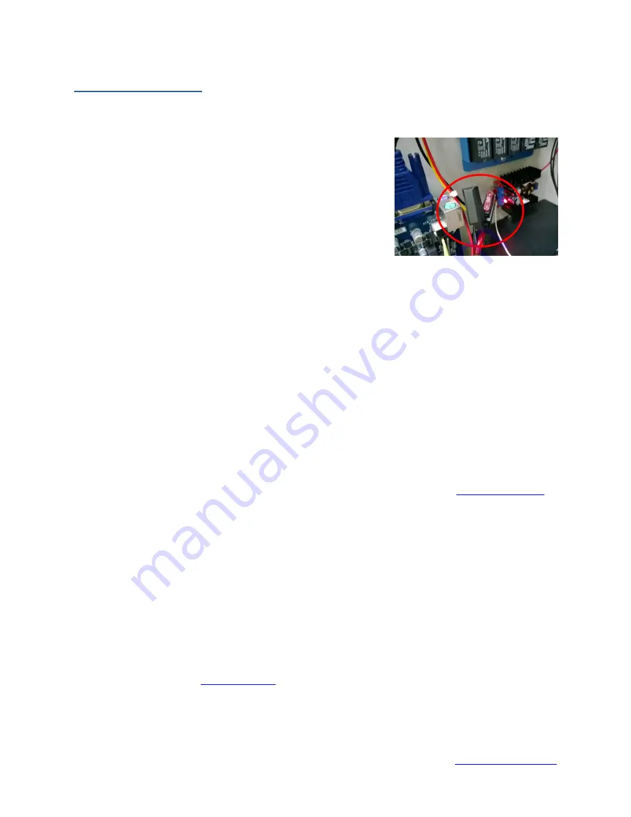
Check the 24V Power Supply and see if the red LED is
turned on. If not, check the fuse close to it. If it is blown,
then the 24V are not supplied to the Motion Controller
(DSPMC or Integra). 24V are required for Digital Inputs and
Outputs.
I can’t enable/arm my Vital CNC Control.
-
Make sure that the operator keys are inserted into the key slot on the front panel and turned
clockwise. Check the error LED on the front panel if it is lit up. This could mean that one of the
Estop Buttons is currently triggered. Estop buttons are sticky switches and will need to be
rotated clockwise to deactivate.
I have wired my drives, but I can’t get any motion.
-
Make sure that the axes are properly configured within the plugin config.
o
Set the Output Type to “Stepper” (Step/Dir), or ”DAC” (+/-10V).
o
Set the Output Index to the correct channel.
o
Set the Control Input Source to “Machxx”.
-
Ensure the “Drive Enable Signal” (Enable1) is mapped to the correct output in the Ports and Pins
Config.
-
Check that the Axes are enabled in the Ports and Pins config (“Motor Outputs” tab).
-
Directions on the setup process and other information can be found in the
I have wired my drives, but I keep getting “Following Error” messages during motion.
-
Make sure that the axis feedback is properly configured in the plugin config.
-
If using Encoders:
o
Set the Feedback Source to “Encoder”.
o
Set the Feedback Index to the correct encoder channel.
o
Use Feedback gain if the “counts per unit” of the encoder is different from that of the
motor’s (i.e. using linear encoders on the milling table). Otherwise, it is set to ‘1’.
For more information, visit


