VISTEK V1679 User Manual Download Page 20

VISTEK V1679 single-mode fibre 

data transceiver 


20 


Issue 1


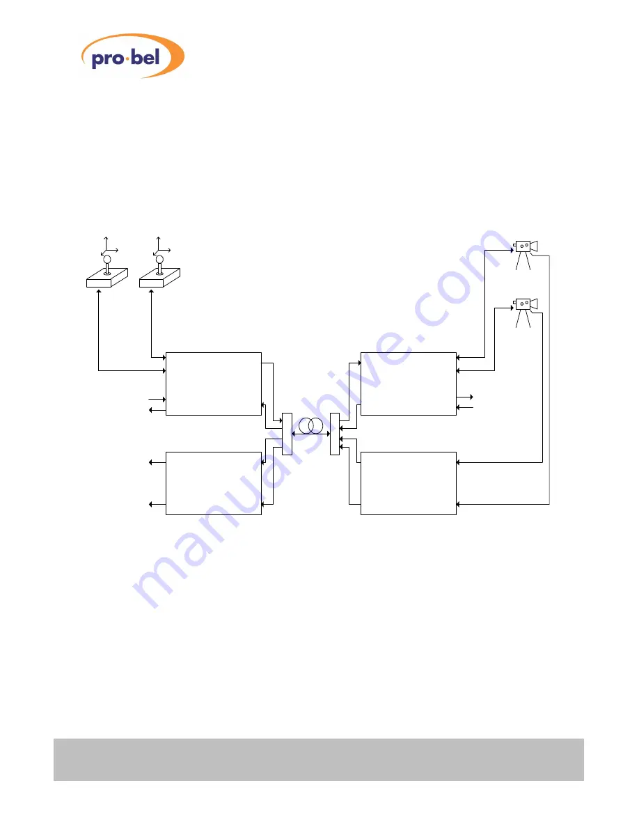
This example illustrates the use of two V1679's for controlling camera tilt-heads through RS-422 at an 
outdoor venue. Assuming that only one fibre link is available, a CWDM module is used for multiplexing/de-
multiplexing different laser wavelengths, in this case not only from the V1679's, but also from a V1673 Dual 
Fibre Transmitter (/TT) and Dual Fibre Receiver (/RR) pair for the actual video link back to the control room. 
 

V1679/xx

V1679/xx

COM1

COM2

RS-422

up to 50km single-mode fibre

GPIO

COM1

COM2

GPIO

Laser Tx

Laser Tx

PIN-TIA Rx

PIN-TIA Rx

Up to 16 GPIO's

Up to 16 GPIO's

RS-422 Camera Control Example using

two V1679 Fibre Data Transceivers

Camera 2

Camera 1

RS-422

(Control Panels and Rack Enclosures are not shown in this diagram)

V1673/RR

V1673/TT

R

S

-4

22

R

S

-4

22

SDI In

SDI In

C
W
D
M

C
W
D
M

Laser Tx

Laser Tx

PIN-TIA Rx

PIN-TIA Rx

SDI Out

SDI Out

Note:

Each Laser Transmitter must emit a different CWDM wavelength!

To other processing modules

Remote Site (e.g. Outdoor Venue)

Local Site (Control Room)

SDI @ 270Mb/s

SDI @ 270Mb/s

Control 2

Control 1


Figure 11 : RS-422 Example 


Summary of Contents for V1679

Page 1: ...1 VISTEK V1679 SINGLE MODE FIBRE DATA TRANSCEIVER USER GUIDE www pro bel com...

Page 2: ...5 4 2 Configuration Options 16 4 2 1 RS 232 422 Mode Selection Jumper 17 4 2 2 Slew rate Selection Jumper Slow Fast 17 4 2 3 Line Termination Jumper RS 422 Only 17 4 3 RS 232 422 Examples 18 5 REAR PA...

Page 3: ...VISTEK V1679 single mode fibre data transceiver HU V1679 3 7 DART INTERFACE 28 7 1 General 28 7 2 DART Control Registers 28 7 3 DART Status Registers 29 8 BLOCK DIAGRAM 30 9 CLEANING INSTRUCTIONS 31...

Page 4: ...t exceed 0 dBm 1mW under normal operating conditions Unused optical outputs are automatically covered with a shutter and prevent direct exposure to the laser beam Even though the power of these lasers...

Page 5: ...ts can be monitored by DART V1679 OP Provides 16 General Purpose Outputs with the choice of 8 Outputs to be either driven externally i e driven through a corresponding signal sent from the remote site...

Page 6: ...Input or locally via DART The polarity of the received control bit for any given output is application dependent hence an unambiguous relationship between input and output polarities doesn t exist One...

Page 7: ...ts V1679 IO 8 Earth free dry contact Relay switches V1679 OP 16 Earth free dry contact Relay switches Contact configuration Normally Open NO or Normally Closed NC Contact material Ag Au Clad Contact r...

Page 8: ...evel buffer with a current sinking sourcing capability of as low as 4mA Extra series resistors might be required when using a voltage source of 7V in order to limit the forward current of the Emitter...

Page 9: ...biased input pins By applying Ohm s law the forward current IF through the LED can be calculated as follows 100 1N4148 F LED F IN F V V V I Considering the worst case scenario by taking VF LED min an...

Page 10: ...it at the far end of the fibre link is unstable for the same period of time The built in Schmitt Trigger Buffer in the Opto Isolator can only tidy up slow rising edges but it cannot suppress heavily b...

Page 11: ...switching cycles A bounce free output is subject to a clean control signal applied at the FET s Gate input 100R 390R 1K8 GPIOn GPIOn 5V 12V 1N4148 Input Bias Voltage Selection Jumper Short to GND Jump...

Page 12: ...mally specified as IC or CollectorCurrent The Transistor must withstand at least 12V minus the voltage drop across the diodes to be precise in the off state normally specified as VCE or Collector Emit...

Page 13: ...e rie s re s is to r is re q u ire d in o rd e r to lim it th e c u rre n t th ro u g h th e C M O S B u ffe r to c o m p ly w ith its s p e c ific a tio n N o te th a t th e B u ffe r s o u tp u t v...

Page 14: ...ator Rating TA 25 C Emitter LED Continuous Forward Current 60mA Input Forward Voltage VF IF 10mA 1 2V typ 1 5V max IF 0 3mA 0 75V min 1 0V typ Turn On Threshold Current IF on 1 6mA max Turn Off Thresh...

Page 15: ...rate and an optional line termination RS 422 only can be configured by setting Jumpers accordingly Data transfer rates of up to 1Mbps in RS 232 mode and 10Mbps in RS 422 mode can be achieved The trans...

Page 16: ...election Jumper RS 232 422 Transceiver Slow COM1 Fast RS232 RS422 RS 232 422 Transceiver Slow COM2 Fast RS232 RS422 Term Term RS422 only RS 232 422 selection Jumper 120Ohm Termination Jumper COM2 exam...

Page 17: ...t two control lines DSR DTR are actually borrowed from COM2 In this mode COM2 can only operate as RS 232 with RxD TxD lines only Factory default setting is RS 232 for COM1 and COM2 4 2 2 Slew rate Sel...

Page 18: ...a so called Null Modem cable RxD TxD CTS RTS and DSR DTR signals crossed over is required for the connection between the PC s Serial Port and the V1679 at the far end If the Serial PC Mouse is equippe...

Page 19: ...iplexing two distinct laser wavelengths V1679 xx V1679 xx COM1 COM2 DART Dongle RS 232 CAN up to 60kmsingle mode fibre GPIO V1606 Rack Local Site V1605 Control Panel CAN V1606 Rack Remote Site COM1 CO...

Page 20: ...control room V1679 xx V1679 xx COM1 COM2 RS 422 up to 50kmsingle mode fibre GPIO COM1 COM2 GPIO Laser Tx Laser Tx PIN TIA Rx PIN TIA Rx Up to 16 GPIO s Up to 16 GPIO s RS 422 Camera Control Example us...

Page 21: ...C T C L A S S 1 T x R x F ib re D ata V 1 6 7 9 Figure 12 V1679 Rear Panel 5 1 Silkscreen Legend and Markings Optical Output Transmitter Optical Input Receiver GPI Connector GPI COMMS I O A label at t...

Page 22: ..._Tx2 RS232 RTS RS422 Tx 3 COM1_Rx1 RS232 CTS RS422 Rx 18 GND 33 COM2_Tx1 RS232 TxD RS422 Tx 4 GPIO_N16 Group B 19 COM1_Tx2 RS232 RTS RS422 Tx 34 GND 5 GPIO_P16 Group B 20 COM1_Tx1 RS232 TxD RS422 Tx 3...

Page 23: ...r a RxD TxD only communication over COM2 where either no flow control is required or a software flow control Xon Xoff is used instead 5 3 V1679 Breakout Adapter Vistek offers a special Breakout Adapte...

Page 24: ...11mm 5 3 3 Power Supply Output The V1679 Breakout Adapter features a power supply output which delivers unregulated 15V 1A fused on a 3 way PHOENIX Header with 3 5mm pitch MCV1 5 3 G 3 5 5 4 Optical...

Page 25: ...ectable options Medium 7dBm typ High 3dBm typ Note Output Power may vary by 1dBm Extinction Ratio 8dB typ Fibre Type Single mode 9 125 m Transmission Length up to 70 km 1550nm 622Mb s CORNING SMF 28 s...

Page 26: ...6 1 1 Remote Control Access and Power Indicators The green V LED is lit when the unit s on board power supply is delivering voltage The yellow REM LED indicates with short blinks that the unit is acc...

Page 27: ...nsmitter is good LED Red Laser Diode Failure Diode has reached end of life or ambient temperature is too high 70 C and the Laser has shut down automatically 6 1 3 Serial Comms Activity Indicators The...

Page 28: ...1 Set 13 DART driven GPI Input6 0 Reset 1 Set 14 DART driven GPI Input7 0 Reset 1 Set 15 DART driven GPI Input8 0 Reset 1 Set 16 Mask Bit for GPI I O1 0 ext controlled 1 DART driven 17 Mask Bit for G...

Page 29: ...5 State of GPI Input8 State of GPI Input8 State of GPI Output16 16 Mask bit for GPI I O1 Mask bit for GPI Input1 Mask bit for GPI Output1 17 Mask bit for GPI I O2 Mask bit for GPI Input2 Mask bit for...

Page 30: ...VISTEK V1679 single mode fibre data transceiver 30 Issue 1 8 BLOCK DIAGRAM Figure 15 Single Mode Fibre GPI O and RS 232 422 Transceiver...

Page 31: ...aturated wipe can be found packed with each board Cleaning Technique Note that pre saturated wipes dry out very quickly and they should be used only once 1 Place the connector ferrule in the wipe and...

Reviews: